
Arrangement for generating actuation force in a centrifugal clutch

a centrifugal clutch and actuation force technology, which is applied in the direction of friction clutches, automatic clutches, clutches, etc., can solve the problem of generating a noticeable impact nois

Inactive Publication Date: 2006-12-05
ZF SACHS AG
View PDF6 Cites 2 Cited by
  • Summary
  • Abstract
  • Description
  • Claims
  • Application Information

AI Technical Summary

Benefits of technology

[0005]It is the object of the present invention to provide an actuation force generating arrangement for a centrifugal clutch in which the striking of the centrifugal members against the housing arrangement due to centrifugal force can be substantially prevented.
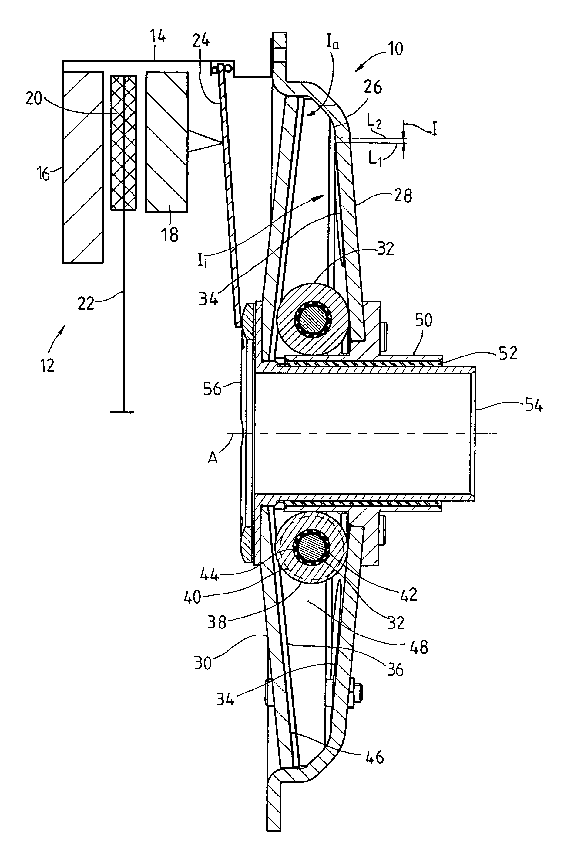
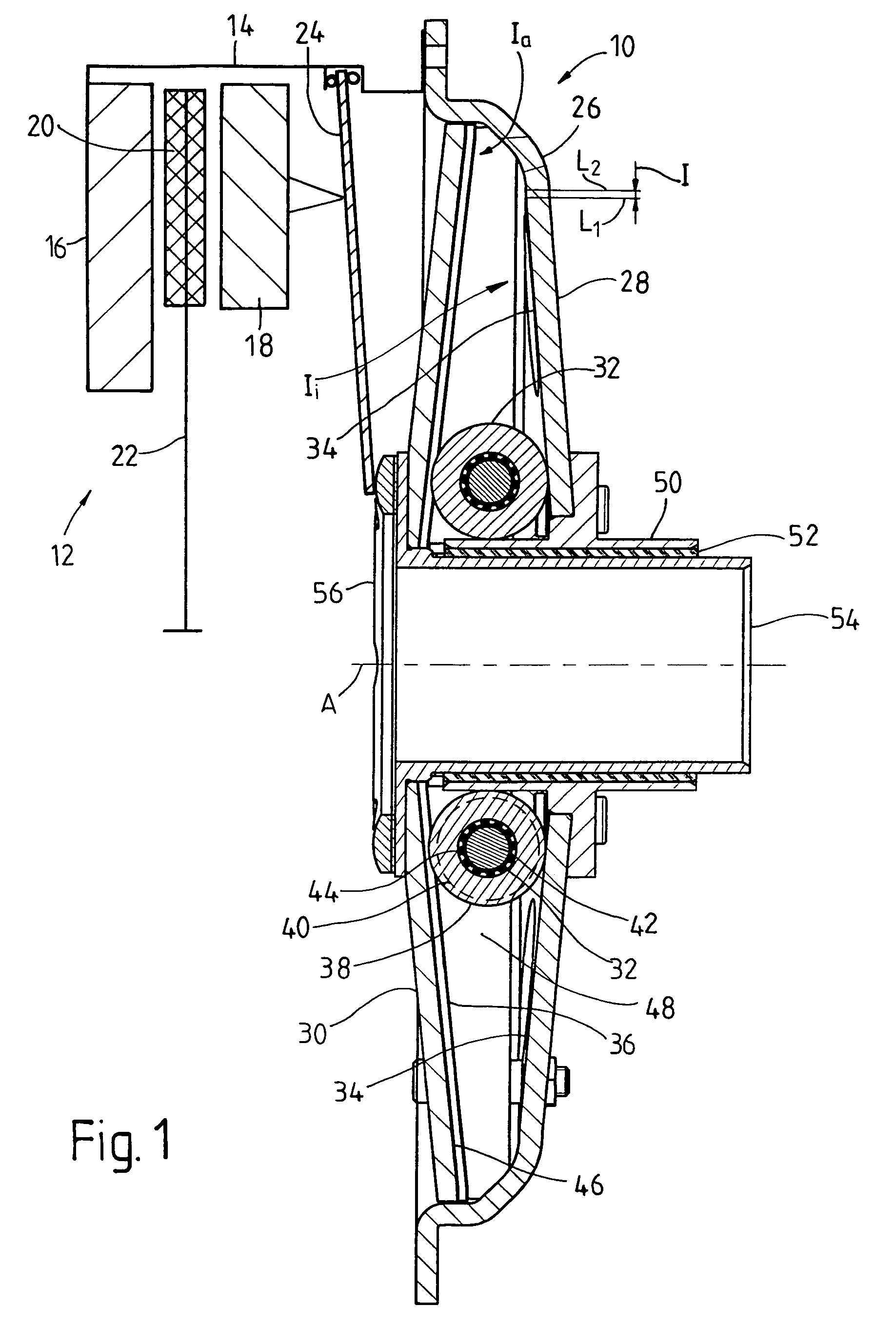
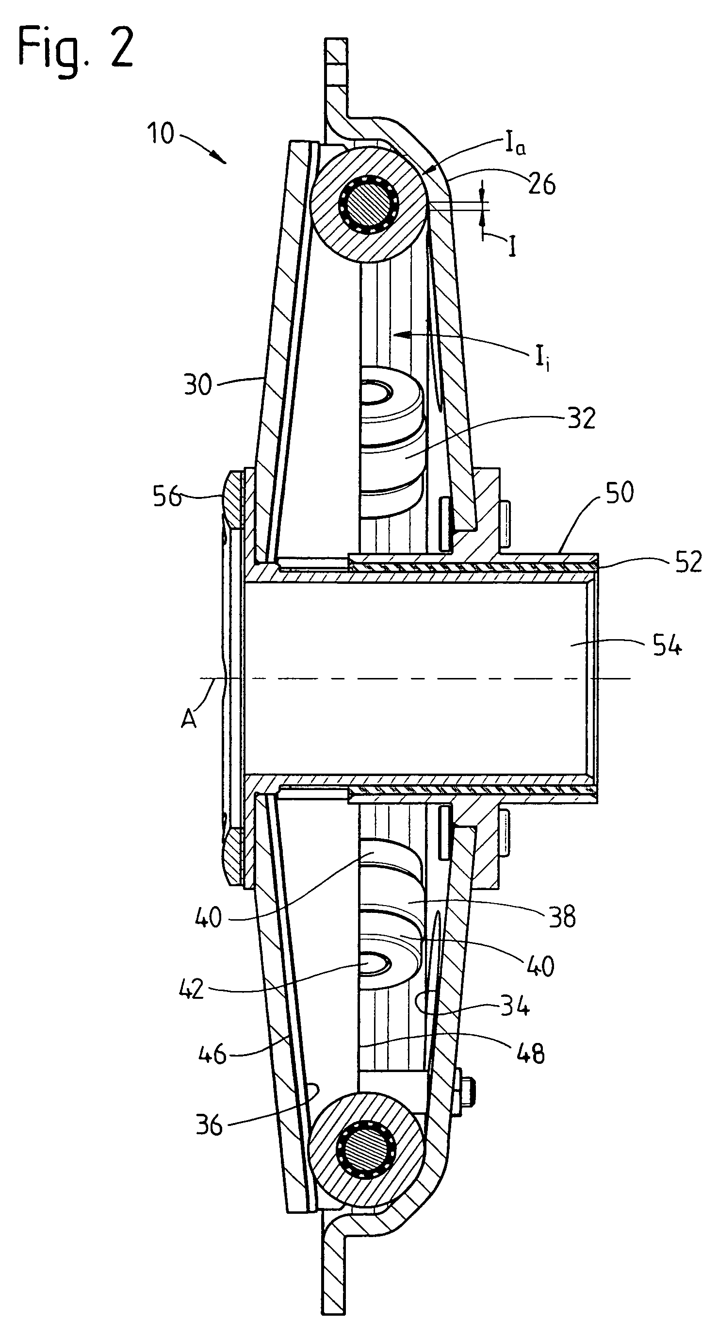
[0007]The present invention utilizes the restraining effect produced by the relative inclination angle between associated supporting areas in order to make possible a smooth transition to a radial end position; that is, the greater the relative inclination angle enclosed between the associated supporting areas, the greater the restraining force opposing the centrifugal action through the two supporting areas. Accordingly, by suitable selection of the relative inclination angle in the radial outer second portion, it can be ensured that the centrifugal members practically never reach a radial outer stop position in the anticipated operating speed range, but rather are always held between the two supporting areas associated with this stop position. Accordingly, any impact noises or impact vibrations can be completely prevented.
[0009]As was already mentioned, it is endeavored in principle to provide a hysteresis effect in centrifugal clutches of this type and in the actuation force generating arrangements for the latter so that when a centrifugal clutch of this kind is fully closed there is no re-releasing or opening of the clutch at those speeds at which the clutch has completely closed, but rather only at appreciably lower speeds. In order to realize this in the present invention also, it is suggested that the relative inclination angle in a transitional portion between the first portion and the second portion is smaller that the relative inclination angle in the first portion.

Problems solved by technology

This contacting of the centrifugal members and housing arrangement generally produces a noticeable impact noise and, moreover, stresses the centrifugal members as well as the housing arrangement.

Method used


Image

  • Arrangement for generating actuation force in a centrifugal clutch
  • Arrangement for generating actuation force in a centrifugal clutch
  • Arrangement for generating actuation force in a centrifugal clutch

Examples


Embodiment Construction

[0015]FIG. 1 shows an actuation force generating arrangement 10, according to the invention, in combination with a friction clutch 12, otherwise indicated only schematically, such as is used in a motor vehicle, particularly in a utility or commercial vehicle, in connection with an automatic transmission. This friction clutch 12 comprises a housing 14, shown schematically, which is fixedly connected to a flywheel 16. In the housing 14 is a pressing plate 18 which is coupled with the housing 14, e.g., by tangential leaf springs or the like which simultaneously also provide a lifting force, so as to be fixed with respect to rotation relative to it but movable in the direction of an axis of rotation A. The friction linings 20 of a clutch disk 22 are arranged between the pressing plate 18 and the flywheel 16. An actuation force transmission element 24 which is constructed as a diaphragm spring, for example, is supported with respect to the housing 14 at the radial outer side in both axia...


PUM


Abstract

An actuation force generating arrangement for a centrifugal clutch includes a housing, a supporting element, and a plurality of centrifugal members. The housing is rotatable about an axis, the housing having a plurality of first supporting areas which each extend radially with respect to the axis. The supporting element is axially movable with respect to the housing and has a plurality of second supporting areas which each extend radially with respect to the axis, each second support area being separated from a respective first support area by an axial distance which decreases with radial distance from the axis. Each of the first and second support areas has a first portion and a second portion which lies radially outside of the first portion, the first and second support areas being inclined with respect to each other at a relative inclination angle which is greater at the second portions than at the first portions. The centrifugal members are supported between respective pairs of first and second support areas, each centrifugal member being radially displaceable by centrifugal force along a respective pair of support areas.

Description

BACKGROUND OF THE INVENTION[0001]1. Field of the Invention[0002]The present invention is directed to an actuation force generating arrangement for a centrifugal clutch including a housing arrangement, a supporting element which is movable axially with respect to the housing arrangement, and a plurality of centrifugal members. Every centrifugal member is supported with respect to the housing arrangement in a first supporting area extending radially from the inside to the outside and is supported with respect to the supporting element in a second supporting area extending radially from the inside to the outside, and every centrifugal member is displaceable radially under the influence of centrifugal force along a pair of supporting areas which comprises a first supporting area and a second supporting area.[0003]2. Description of the Related Art[0004]A centrifugal clutch for use in motor vehicles is known from DE 32 20 572 A1. The roller elements acting as centrifugal members comprise ...

Claims


Application Information

Patent Timeline
Patent Type & Authority Patents(United States)
IPC IPC(8): F16D43/04F16D43/08
CPCF16D43/08
Inventor STURMER, WINFRIEDWEIDINGER, REINHOLD
Owner ZF SACHS AG
Learn More