
Digital light processing projector

a technology of digital light processing and projectors, applied in projectors, instruments, optics, etc., can solve the problems of difficult achieve the effect of not easy to alter the quality of projection, small size and light weigh

Active Publication Date: 2006-12-05
DELTA ELECTRONICS INC
View PDF3 Cites 9 Cited by
  • Summary
  • Abstract
  • Description
  • Claims
  • Application Information

AI Technical Summary

Benefits of technology

[0011]Therefore, the present invention is directed to a digital light processing (DLP) projector with light weight and small size. In addition, projection quality is not easily altered by temperature variations.
[0018]Accordingly, in the DLP projector of the present invention, the light from the light source has been split into a red color light, a green color light and a blue light by the splitter component before the light is incident to the TIR prisms. The three color lights are combined by a device that includes two dichroic beam splitters. It should be noted that, this device with two beam splitters, such as a X-cube, is lighter, smaller, cheaper, and has a shorter light path than the conventional Philips prism. Therefore, the weight of the DLP projection device can be greatly reduced. In addition, the quality of projection can be improved due to the shorter light path. Moreover, the influence of thermal diffractions of the two-way lens in the present invention is slighter compared with the conventional Philips prism. Therefore, the influence of temperature variations on the projection quality may be reduced to the minimum.

Problems solved by technology

In addition, projection quality is not easily altered by temperature variations.

Method used


Image

  • Digital light processing projector
  • Digital light processing projector
  • Digital light processing projector

Examples


Embodiment Construction

[0028]The present invention now will be described more fully hereinafter with reference to the accompanying drawings, in which embodiments of the invention are shown. This invention may, however, be embodied in many different forms and should not be construed as limited to the embodiments set forth herein; rather, these embodiments are provided so that this disclosure will be thorough and complete, and will fully convey the scope of the invention to those skilled in the art. Like numbers refer to like elements throughout.

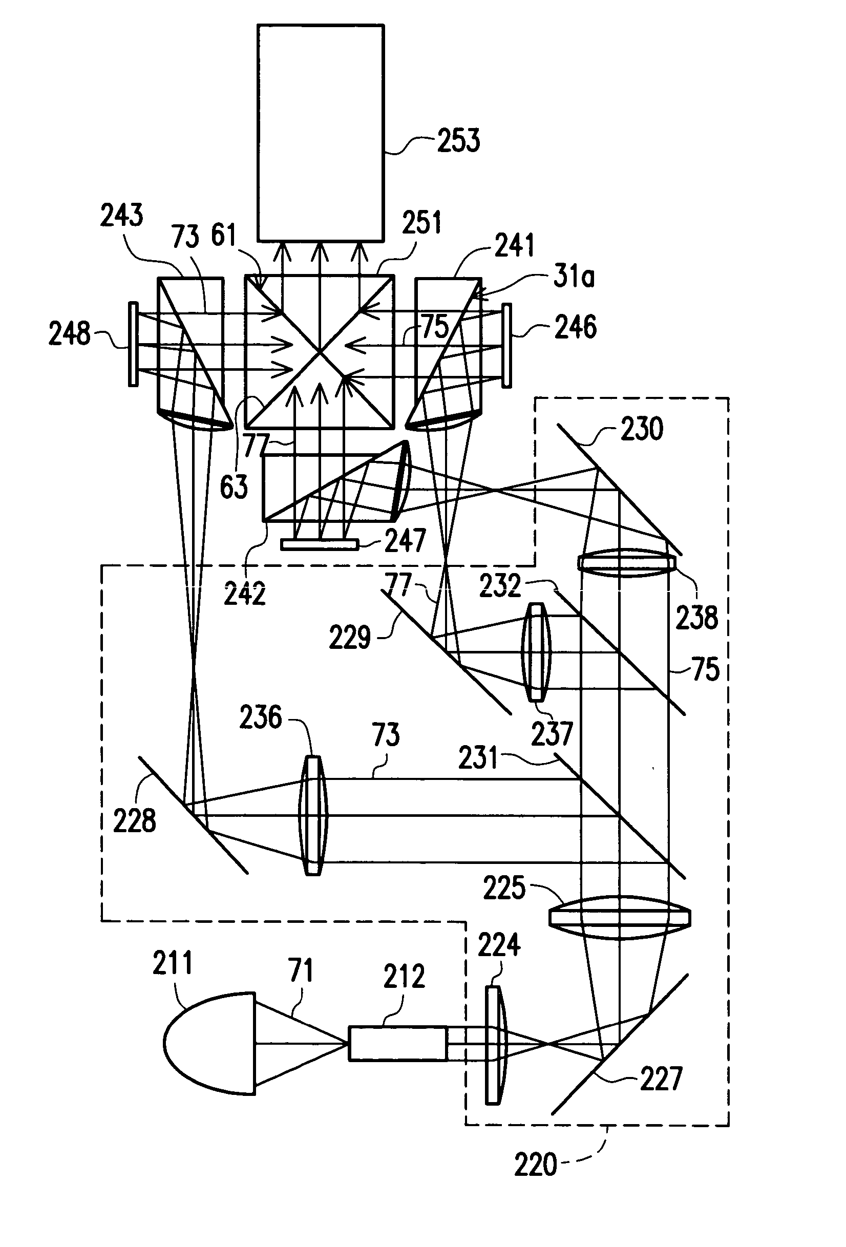
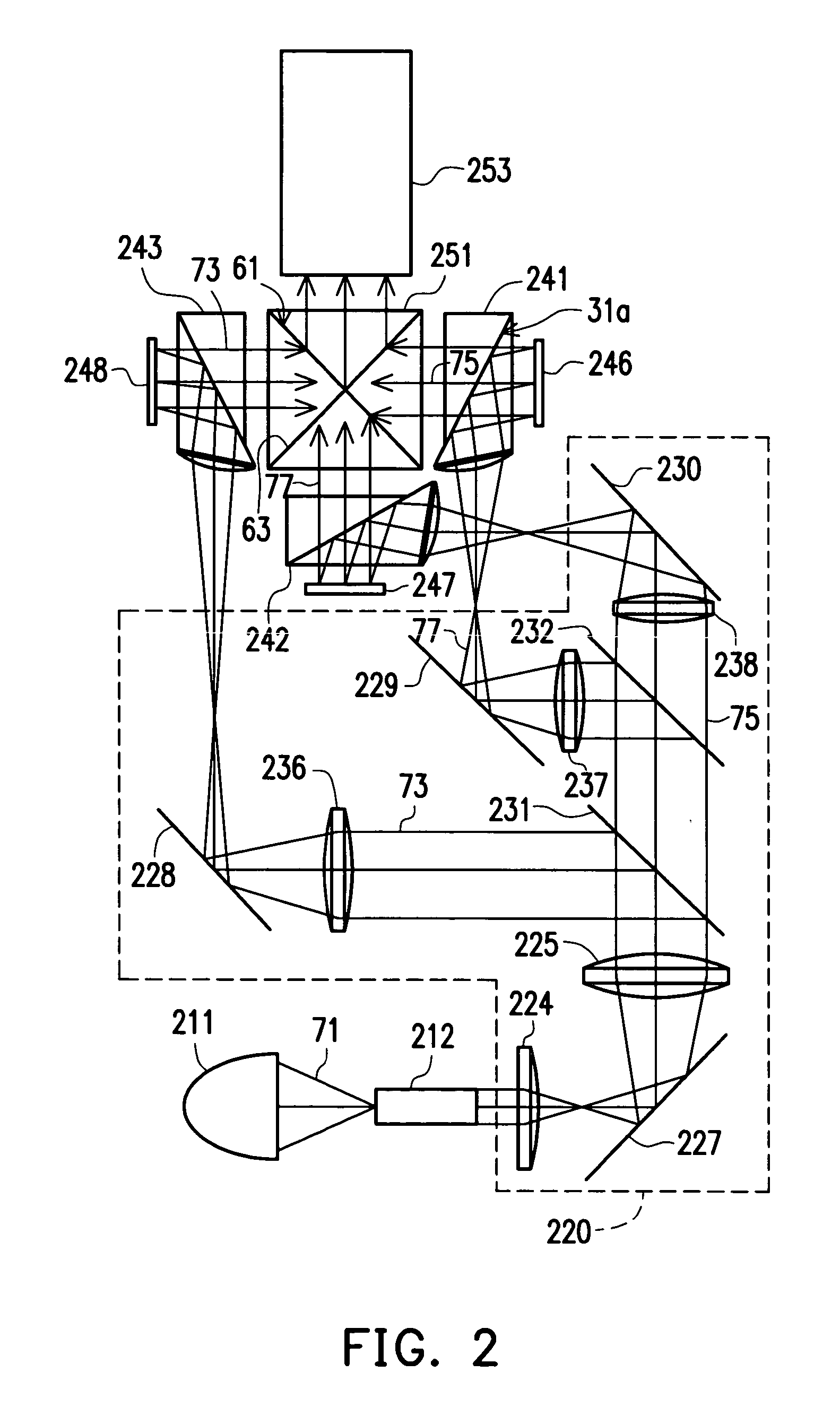
[0029]FIG. 2 is a schematic plan view of a DLP projector according to one embodiment of the present invention. Please refer to FIG. 2. A DLP projector comprises, for example but not limited to, a light source 211, a splitter module 220, total internal reflection (TIR) prisms 241, 242, and 243, digital mirror devices 246, 247, and 248, a combiner 251 and a projection lens 253. Wherein, the light source 211 can comprise a cold cathode fluorescence bulb. In one embodim...


PUM


Abstract

A digital light processing projector comprising a light source, a splitter module, a plurality of total internal reflection (TIR) prisms and digital mirror devices (DMDs), a combiner and a projection lens is provided. The splitter module is disposed in the light path of the light after the light source to split the light into a plurality of color lights. Each color light is incident to the total reflection plane of the TIR prism with an incident angle larger than the critical angle, and then is totally reflected to the DMD. Thereafter, each color light is reflected by the DMD being incident to the total reflection plane of the TIR prism with an incident angle smaller than the critical angle, and then passes through the TIR prism directly. The color lights passing through the TIR prisms are combined by the combiner and then projected by the projection lens.

Description

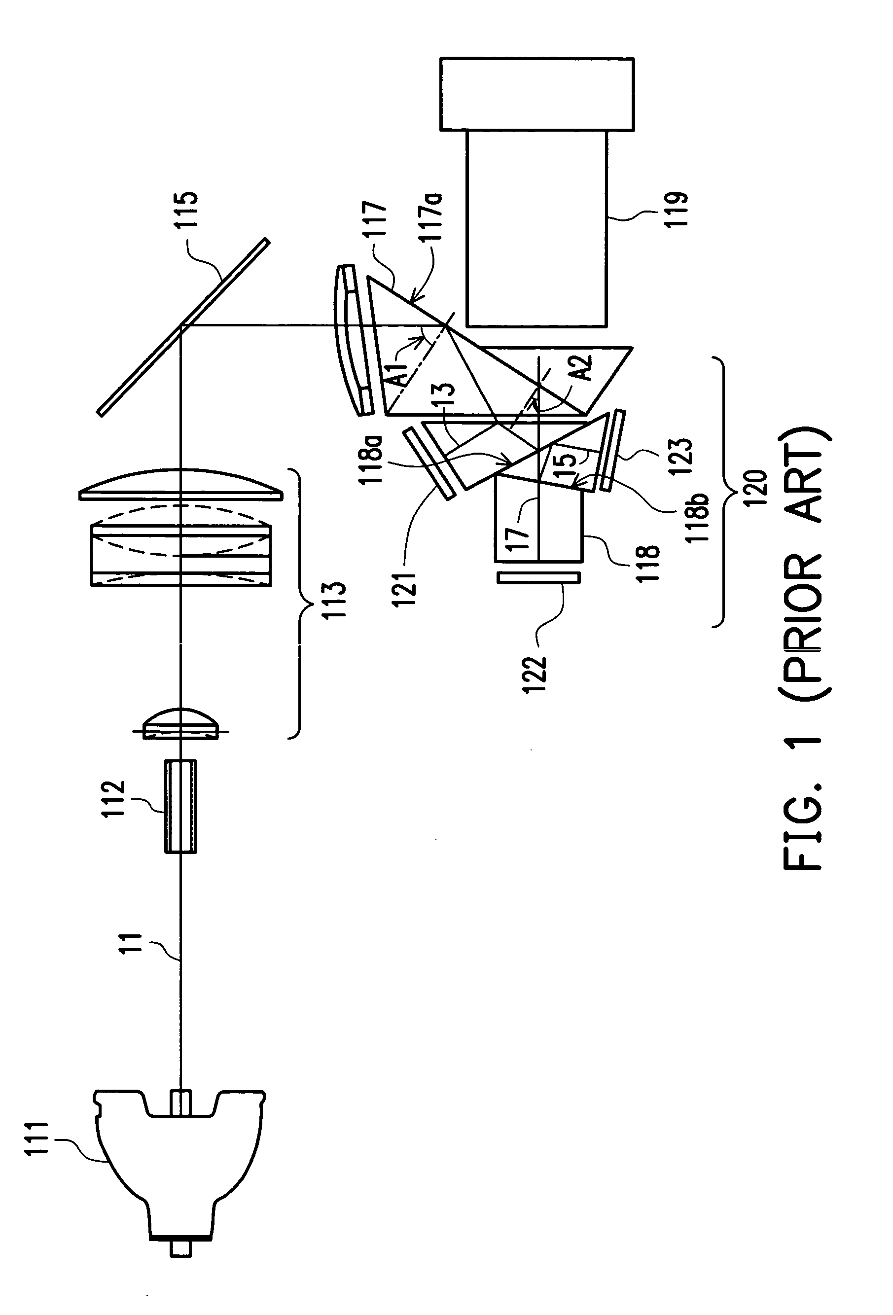
CROSS-REFERENCE TO RELATED APPLICATION[0001]This application claims the priority benefit of Taiwan application serial no. 92125461, filed on Sep. 16, 2003.BACKGROUND OF THE INVENTION[0002]1. Field of the Invention[0003]The present invention relates to a digital light processing (DLP) projector. More particularly, the present invention relates to a DLP projector without any special optical component such as the conventional Philip prism.[0004]2. Description of Related Art[0005]In a conventional digital light processing (DLP) projector, a key component called “digital mirror device” (DMD) is the fundamental semiconductor component, which is controlled by two-bit pulse modulation. The chip of the digital mirror device is adopted for controlling the digital optical switch by rapidly and precisely reflecting the light source. Unlike the conventional liquid crystal projector that modulates the light by using liquid crystal (LCD) to change the polarization state, DLP projector uses the ref...

Claims


Application Information

Patent Timeline
Patent Type & Authority Patents(United States)
IPC IPC(8): G03B21/00G03B21/26G03B21/28G02B26/08
CPCG03B21/00G03B21/005
Inventor HUANG, JUNEJEI
Owner DELTA ELECTRONICS INC
Learn More