Massive security barrier
- Summary
- Abstract
- Description
- Claims
- Application Information
AI Technical Summary
Benefits of technology
Problems solved by technology
Method used
Image

Examples
first embodiment
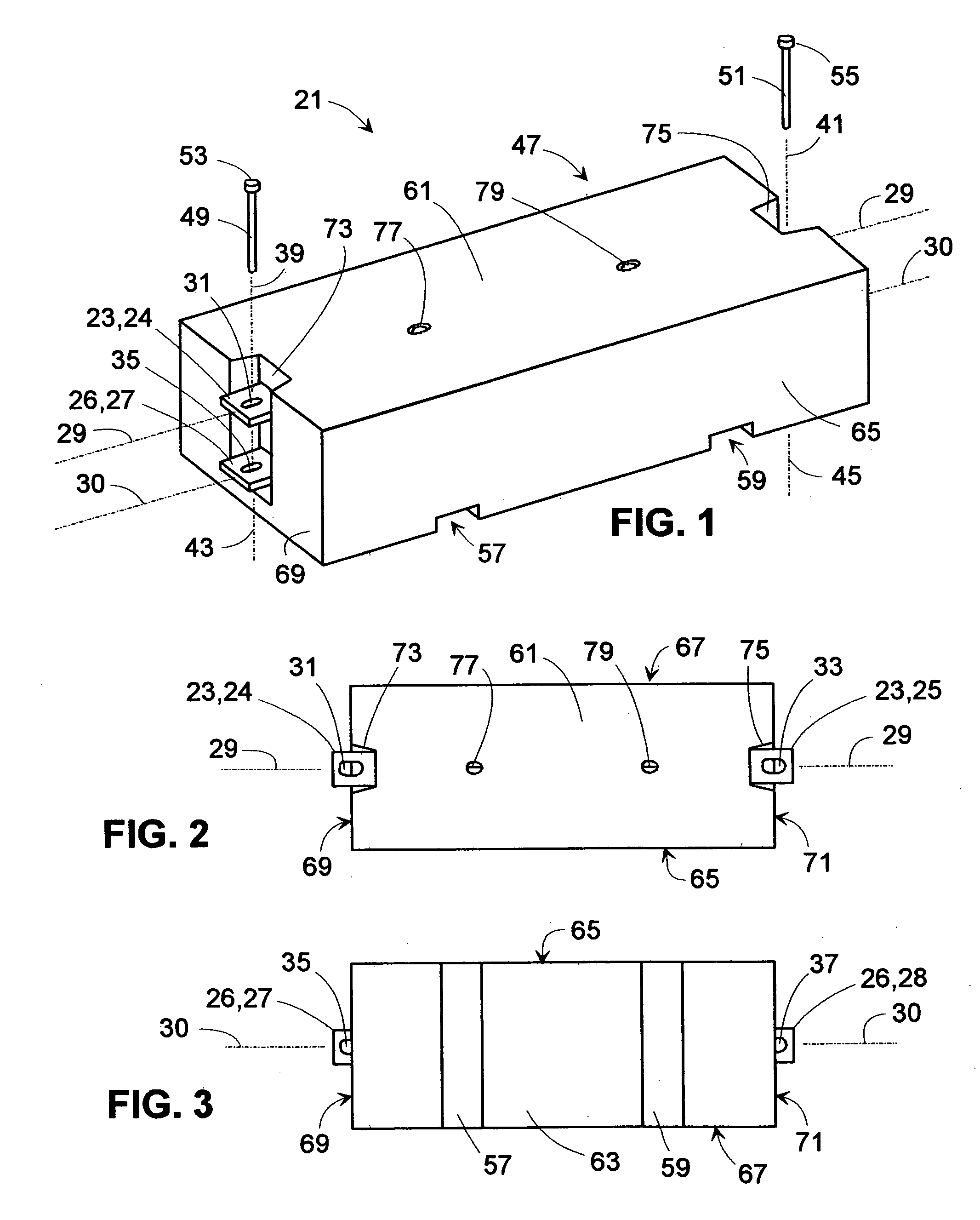
[0050]FIG. 1 shows a massive security barrier element 21 comprising a mass of solid material 47 surrounding a first tie-bar 23 and a second tie-bar 26. The two tie-bars or beams 23 and 26 have respectively a first longitudinal axis 29 and a second longitudinal axis 30 which are at least approximately parallel to one another (within about 6 degrees of parallelism). Note that the two tie-bars 23 and 26 are spaced apart from one another. The first tie-bar 23 is shown as having a first attachment hole 31 in an exposed first end or tongue 24 at the left side of the view. This first tie-bar 23 also has a second attachment hole 33 in a second end or tongue 25 (at the right-hand side of the view but not shown until FIG. 2) at an opposite end 25 longitudinally. The second tie-bar 26 is shown as having a third attachment hole 35 in an exposed first end or tongue 27 at the right-hand side of the view. This second tie-bar 26 also has a fourth attachment hole 37 in a fourth end or tongue 28 at a...
second embodiment
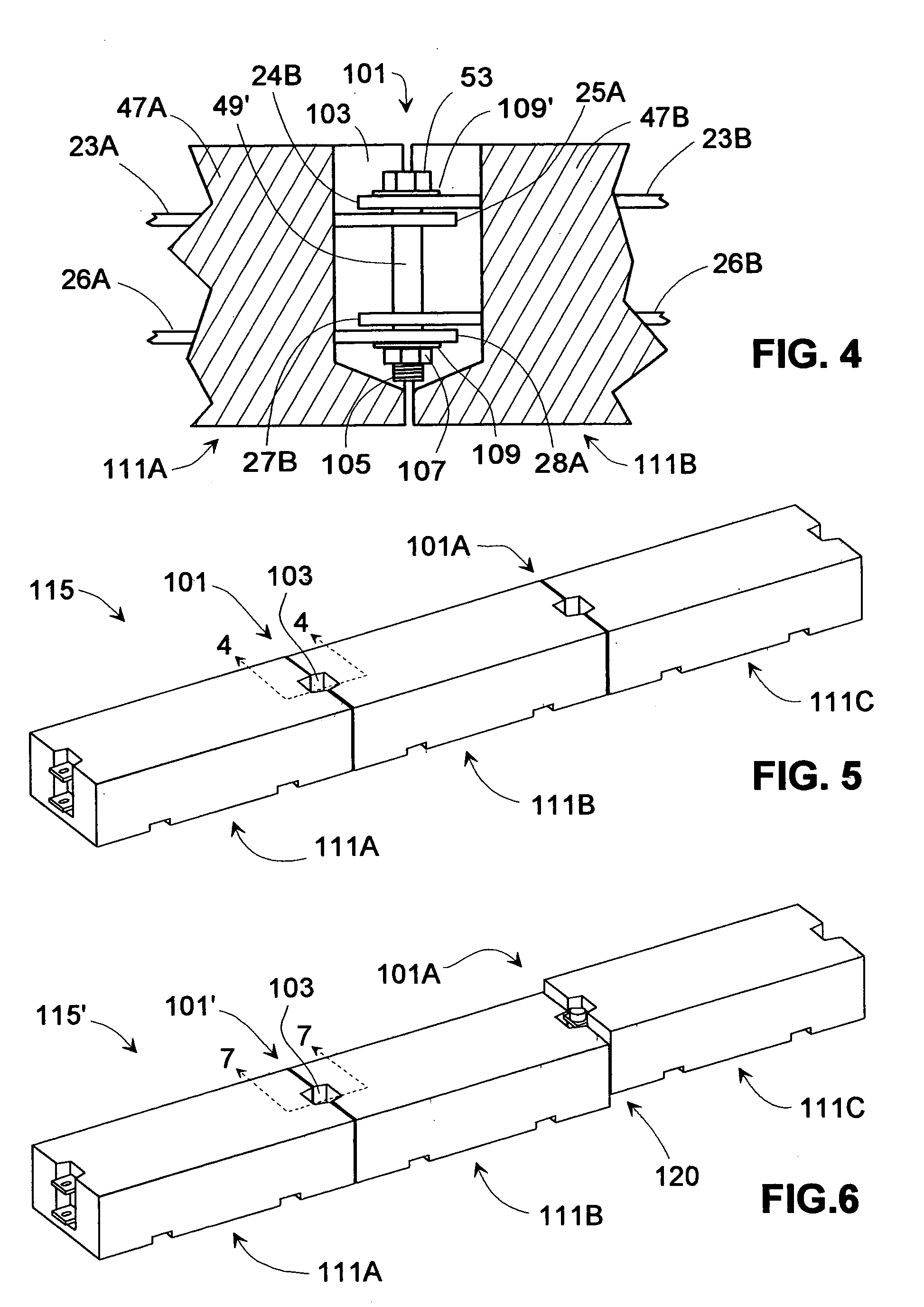
[0069]FIG. 8 shows a barrier wall 115″ illustrated as a row of three barrier elements 113A, 113B, and 113C aligned longitudinally end-to-end. The three massive security barrier elements 113A, 113B, and 113C are all barrier elements of a second embodiment having mutually offset tie-bar locations 125. The sectional view of FIG. 10 illustrates details of a fourth coupling means at the inter-barrier coupling 101″. Inter-barrier cavities are illustrated, as for example the inter-barrier cavity 103′ formed between the right-hand end of barrier element 113A and the left-hand end of barrier element 113B. An identical inter-barrier coupling to that of 101″ is shown between barrier elements 113B and 113C.
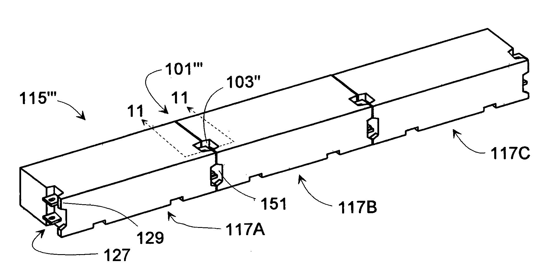
[0070]FIG. 9 shows a barrier wall 115′″ illustrated as a row of three barrier elements 117A, 117B, and 117C aligned longitudinally end-to-end. The three massive security barrier elements 117A, 117B, and 117C are all barrier elements of a third embodiment having tie-bar located in a forward ti...
third embodiment
[0075]FIG. 11 is a sectional view from FIG. 9 of the inter-barrier coupling 101″′ and the inter-barrier cavity 103″. FIG. 11 shows the fifth coupling means used to secure together the two adjacent barrier elements 117A and 117B of the The left-hand-side of the view shows the right-hand end of the first barrier element 117A, while the right-hand-side of the view shows the left-hand end of the second barrier element 117B. The solid masses of material 47A″ and 47B″ comprising respective barrier elements 117A and 117B are also shown. Tie-bars 23A″ and 26A″, with ends or tongues 25A″ and 28A″ respectively, are shown with the barrier element 117A. Tie-bars 23B″ and 26B″, with ends or tongues 24B″ and 27B″ respectively, are shown with the barrier element 117B. Note that the ends 25A″ and 28A″ of the two respective tie-bars 23A″ and 26A″ from the barrier element 117A on the left-hand-side of the view are both between the ends 24B″ and 27B″ of the two respective tie-bars 23B″ and 26B″from t...
PUM
 Abstract
Description
Claims
Application Information
 - R&D
- Intellectual Property
- Life Sciences
- Materials
- Tech Scout
- Unparalleled Data Quality
- Higher Quality Content
- 60% Fewer Hallucinations
Browse by: Latest US Patents, China's latest patents, Technical Efficacy Thesaurus, Application Domain, Technology Topic, Popular Technical Reports.
© 2025 PatSnap. All rights reserved.Legal|Privacy policy|Modern Slavery Act Transparency Statement|Sitemap|About US| Contact US: help@patsnap.com