Rowing oar system

a technology of oars and rigging, which is applied in the direction of waterborne vessels, marine propulsion, vessel construction, etc., can solve the problem of not doing anything to solve the problem of maximizing efficiency

Inactive Publication Date: 2006-12-05
HORAN RICHARD +1
View PDF5 Cites 9 Cited by
  • Summary
  • Abstract
  • Description
  • Claims
  • Application Information

AI Technical Summary

Benefits of technology

[0012]The relationship between the orientation of the blade in the water and the boat's direction of travel is critical to achieving a powerful, efficient stroke. Keeping the blade square to the water as it is pulled through the water reduces power loss due to water sliding off of an angled blade, as is the case in a conventional set-up.
[0029]The present invention also improves the state of the art by incorporating a system for easily changing the oar's handles and blades. Traditional oars make no provisions for interchanging handles and blades of different sizes and shapes. To change the handle and / or blade, the oar itself usually must be changed. It is further the object of the present invention to provide a method for increasing the stiffness and reducing the weight of the oar shafts.

Problems solved by technology

While these patents describe feathering systems, they do nothing to solve the problem of maximizing efficiency in the oar stroke itself.

Method used


Image

  • Rowing oar system
  • Rowing oar system
  • Rowing oar system

Examples


Embodiment Construction

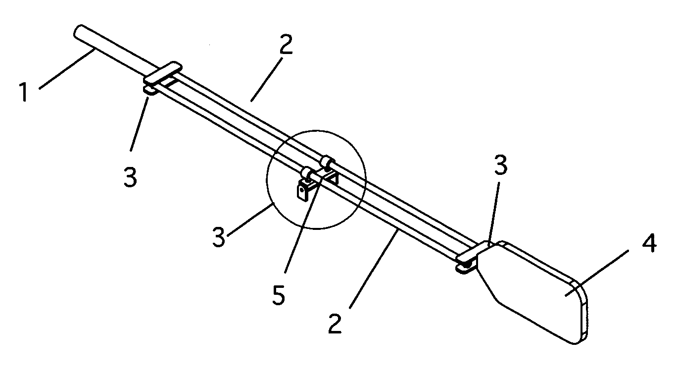
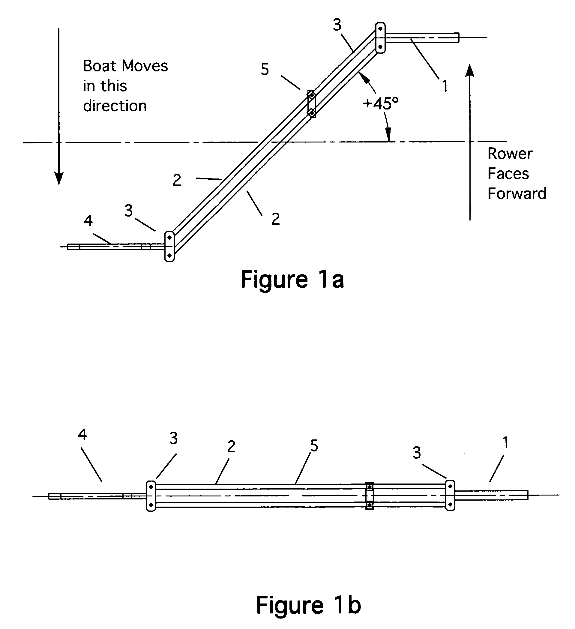
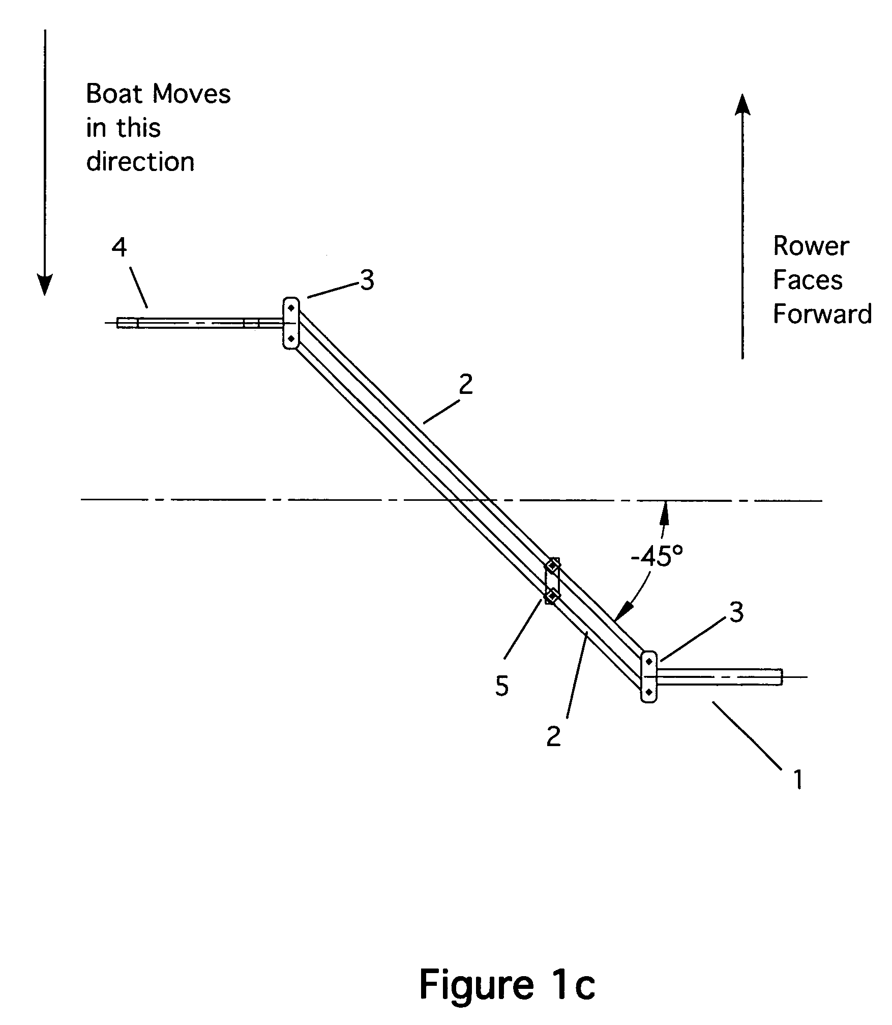
[0063]Referring now to FIGS. 1a, 1b. 1c, 2 and 3, the new oar system is shown. The oar system is made up of a handle 1, a pair of oar shafts 2, of equal length; two end connectors 3 and a blade 4. Note that the oar shafts are pivotably attached to the end connectors so that as the handle is moved, the oar shafts move about to create a parallelogram configuration, as shown in FIGS. 1a, 1b and 1c. An oarlock 5 is shown at a central point. The oarlock 5 allows the oar shafts to rotate as shown. The oarlock also allows the oar to move vertically, as discussed below. The oarlock 5 is shown in its preferred position, which is about ⅓ of the way down the shaft from the handle. However, the oarlock 5 can be positioned at other places along the shaft (if desired). See, e.g., FIGS. 4 and 5.

[0064]In FIG. 1a, the direction of the rower and the direction of the travel of the boat are indicated by the arrows. The rower pulls rearward on the handle 2 (as indicated by the arrow). At the beginning o...


PUM


Abstract

An oar consisting of two parallel shafts linked on both ends to form a parallelogram configuration, which keeps the oar's blade and handle parallel to one another and perpendicular to the boat throughout the rowing cycle. The system is further enhanced to provide an internal, adjustable feathering system, interchangeable handles and blades and an integrated, quick-release oarlock.

Description

CROSS REFERENCE TO RELATED APPLICATIONS[0001]Not ApplicableSTATEMENT REGARDING FEDERALLY SPONSORED RESEARCH AND DEVELOPMENT[0002]Not ApplicableBACKGROUND OF THE INVENTION[0003]1. Field of the Invention[0004]The present invention relates to a rowing apparatus having an oar and oarlock and particularly to a rowing apparatus having improved efficiency.[0005]2. Description of the Prior Art[0006]Conventional rowing systems use oars with handles and blades that are solidly fixed to and inline with the oar shaft. An oarlock is positioned about a third of the way down the shaft between the handle and blade. The oarlock acts as a fulcrum about which the oar pivots. As the handle is pulled by the rower, the blade on the opposite end of the oar is pulled through the water in an arc, thereby propelling the boat.[0007]As the rower moves the oar through the power stroke, the oar handle and blade are perpendicular to the rower and the boat for a brief instant. Because the most efficient transfer o...

Claims


Application Information

Patent Timeline
Patent Type & Authority Patents(United States)
IPC IPC(8): B63H16/04
CPCB63H16/04
Inventor HORAN, RICHARDGUARINO, KERRY
Owner HORAN RICHARD
Why Eureka
Try Eureka