Microwave cooker having antenna in cooperation with movable stirrer

a microwave cooker and stirrer technology, which is applied in the direction of domestic stoves or ranges, electric/magnetic/electromagnetic heating, lighting and heating apparatus, etc., can solve the problems of difficult to clean food particles inside the gap below the turn table, food is not uniformly heated and cooked, and the inside of the cooking chamber becomes dirty easily, so as to achieve uniform heating and cooking food, and effectively emit microwave

Inactive Publication Date: 2006-12-05
LG ELECTRONICS INC
View PDF3 Cites 36 Cited by
  • Summary
  • Abstract
  • Description
  • Claims
  • Application Information

AI Technical Summary

Benefits of technology

The present invention is a microwave cooker that can cook food evenly by emitting microwave in a cooking chamber. It does this by first rotating a rotation antenna with a driving motor to emit microwave, and then sliding a movable stirrer linearly with the rotation antenna to further enhance the heating process. This results in a more complete and uniform cooking of food.

Problems solved by technology

The technical problem addressed in this patent is the non-uniform heating and cooking of food in conventional microwave cookers, which can result in food particles remaining in the gap below the turn table and making it difficult to clean the cooking chamber.

Method used


Image

  • Microwave cooker having antenna in cooperation with movable stirrer
  • Microwave cooker having antenna in cooperation with movable stirrer
  • Microwave cooker having antenna in cooperation with movable stirrer

Examples


first embodiment

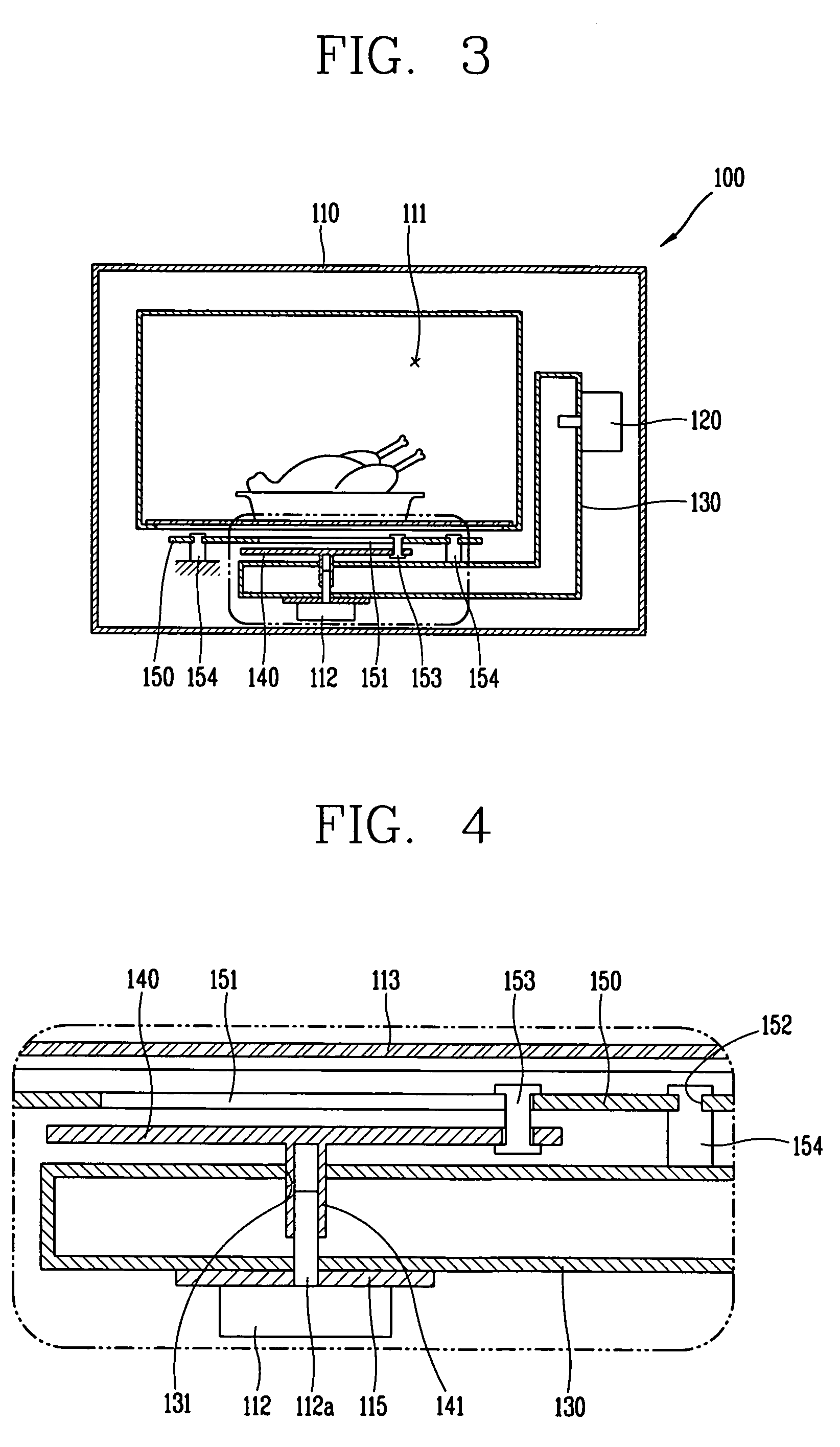
[0031]As shown, a microwave cooker 100 according to the present invention comprises a body 110 having a cooking chamber 111 therein, a microwave source 120 disposed at the body 110 for generating microwave; a wave guide 130 for guiding microwave generated from the microwave source 120 into the cooking chamber 111, a rotation antenna 140 installed in the body 110 to be rotatable by a driving motor 112 for emitting microwave guided by the guide wave 130 into the body 110, and a movable stirrer 150 coupled to the rotation antenna 140 so as to be interworked with the rotation antenna 140, and movable in back and forth directions of the cooking chamber 111.

[0032]An adjustment unit (not shown) is installed at one outer side of the body 110, and a door (not shown) is openably installed at another outer side of the body 110. A table 113 is installed at a floor of the cooking chamber 111.

[0033]The movable stirrer 150 is provided with a first guide slot 151 at a center thereof in a longitudin...

second embodiment

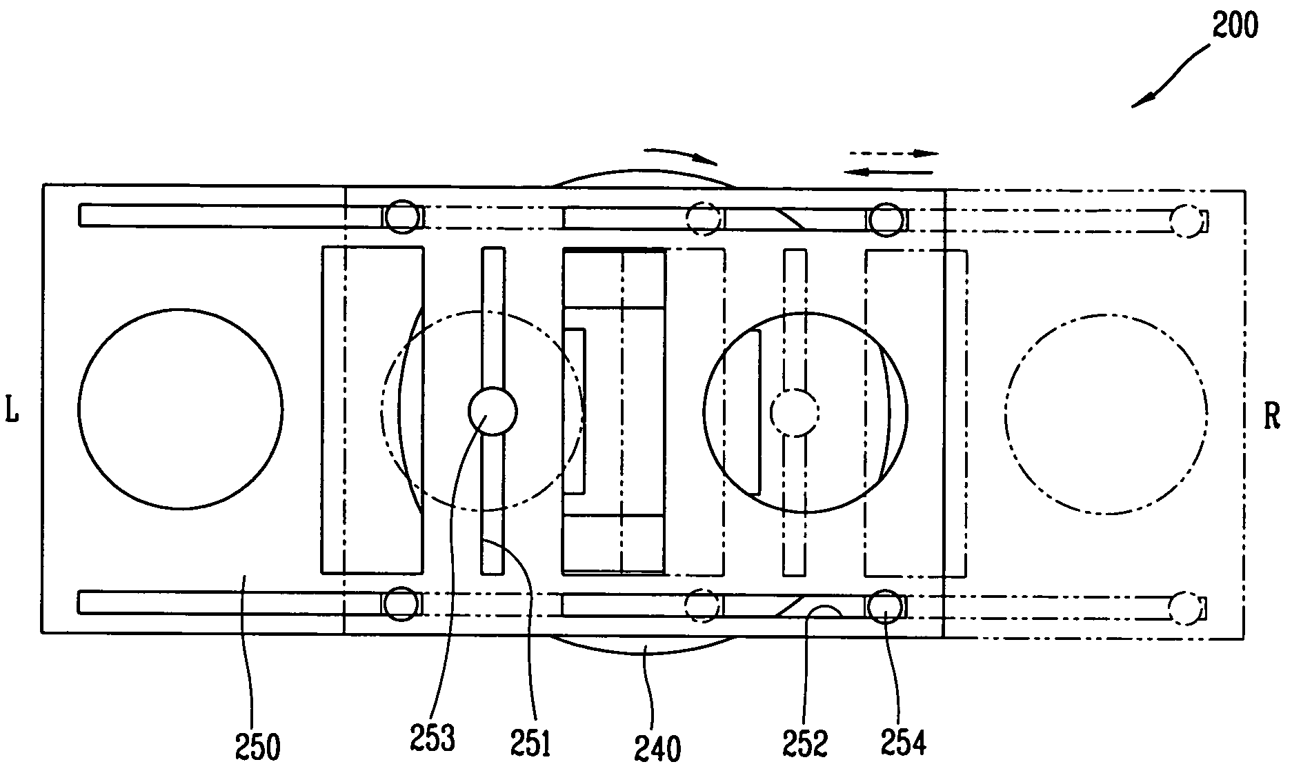
[0053]An operation of the microwave cooker according to the present invention will be explained as follows.

[0054]A user puts food to be cooked on a table (not shown) of the cooking chamber 211, and closes a door (not shown). Then, the user operates an adjustment unit (not shown), so that microwave generated from the microwave source 220 is introduced into the cooking chamber 211 through the wave guide 230, the rotation antenna 240, and the movable stirrer 250. The microwave guided into the cooking chamber 211 is absorbed into the food disposed on the table, thereby heating and cooking the food.

[0055]The movable stirrer 250 is formed to have an emission area wider than that of the rotation antenna 240, and is disposed to be movable in right and left directions of the cooking chamber 211 by the rotation antenna 240, thereby uniformly emitting microwave in the cooking chamber 211 and forming a resonant mode. Accordingly, the food can be uniformly heated.

[0056]Referring to FIG. 13, an o...


PUM


Abstract

A microwave cooker includes a body having a cooking chamber therein, a microwave source disposed at the body for generating a microwave, a wave guide for guiding the microwave generated from the microwave source into the cooking chamber, a rotation antenna installed in the body to be rotatable by a driving motor for emitting the microwave guided by the wave guide into the cooking chamber, and a movable stirrer coupled to the rotation antenna so as to be interworked with the rotation antenna.

Description


Claims


Application Information

Patent Timeline
Owner LG ELECTRONICS INC
Why Eureka
Try Eureka