Integration of three dimensional scene hierarchy into two dimensional compositing system

a compositing system and scene technology, applied in the field of computer graphics, can solve the problems of inability to maintain the refresh rate of hardware, the limitation of the traditional model of accessing graphics on the computer system, and the current model of preparing frames using bitmaps requires too much data processing to achieve the effect of ensuring the smooth transition of frames

Inactive Publication Date: 2006-12-05
MICROSOFT TECH LICENSING LLC
View PDF4 Cites 80 Cited by
  • Summary
  • Abstract
  • Description
  • Claims
  • Application Information

AI Technical Summary

Problems solved by technology

The limits of the traditional model of accessing graphics on computer systems are being reached, in part because memory and bus speeds have not kept up with the advancements in main processors and / or graphics processors.
In general, the current model for preparing a frame using bitmaps requires too much data processing to keep up with the hardware refresh rate when complex graphics effects are desired.
As a result, when complex graphics effects are attempted with conventional graphics models, instead of completing the changes that result in the perceived visual effects in time for the next frame, the changes may be added over different frames, causing results that are visually undesirable.
Further, this problem is aggravated by the introduction of three dimensional (3D) graphics and special effects such as animation of the 3D images being displayed.

Method used


Image

  • Integration of three dimensional scene hierarchy into two dimensional compositing system
  • Integration of three dimensional scene hierarchy into two dimensional compositing system
  • Integration of three dimensional scene hierarchy into two dimensional compositing system

Examples


Embodiment Construction

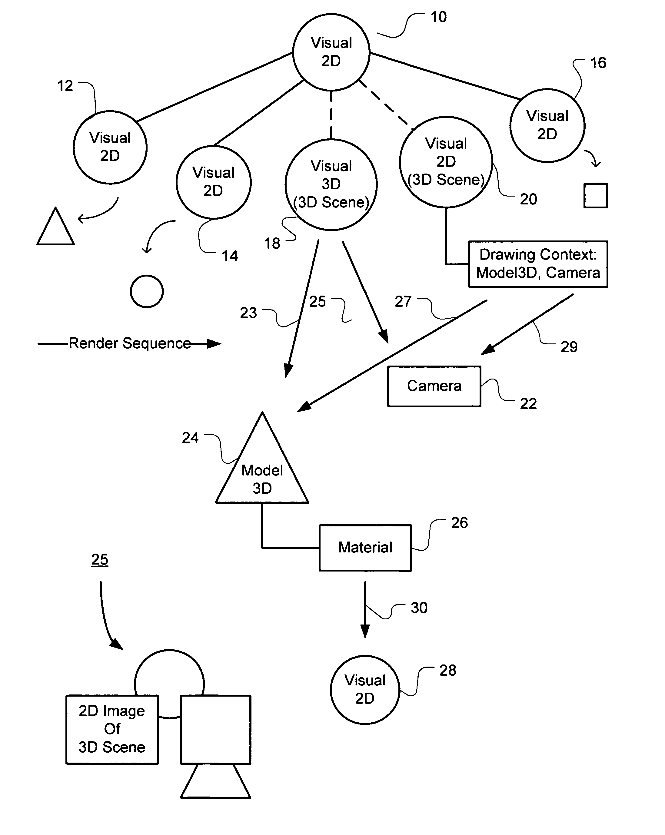
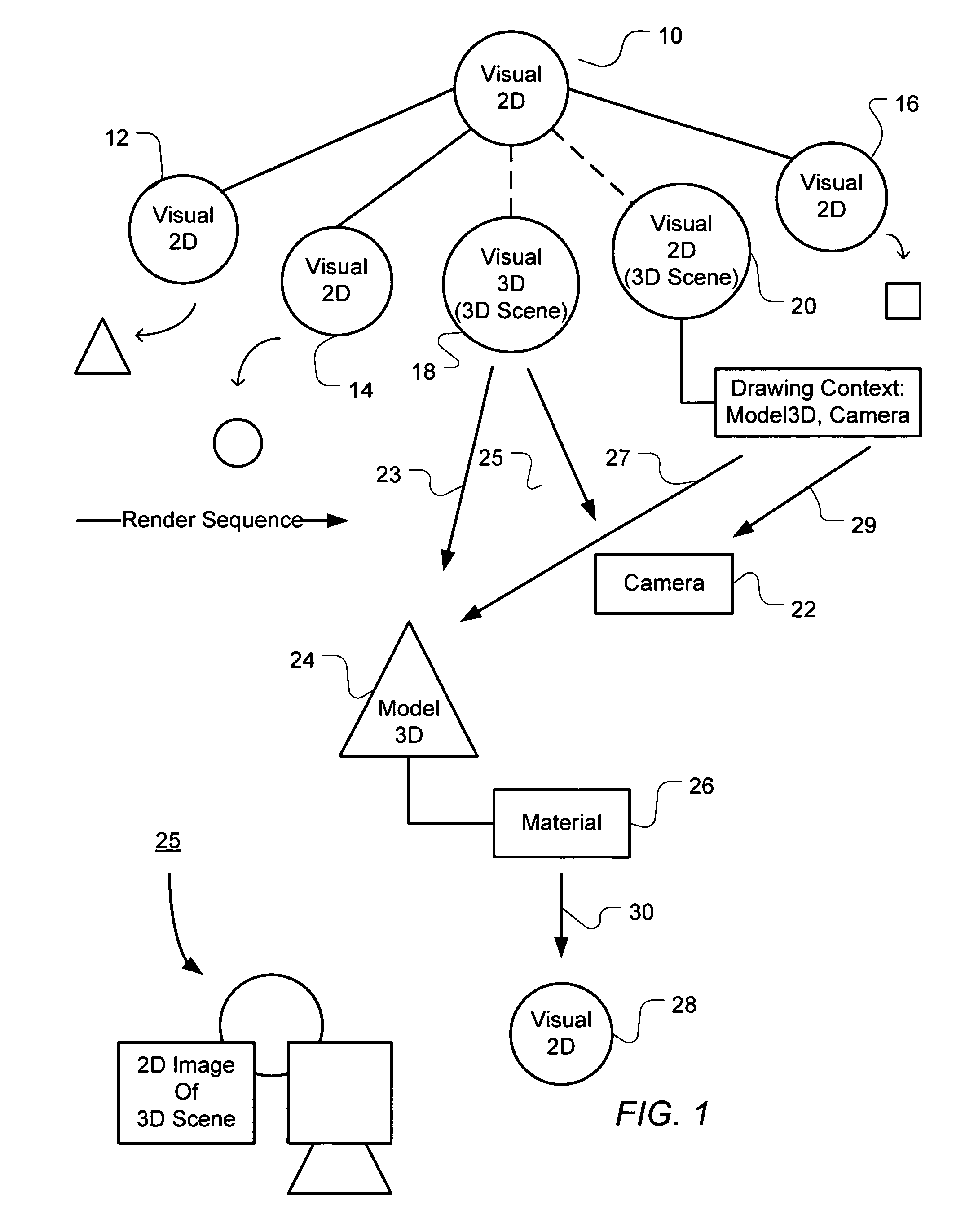
[0020]In accordance with one embodiment of the invention, FIG. 1 illustrates 3D reference or scene objects integrated into a visual objects tree hierarchy so that the tree has both visual 2D objects and 3D reference or scene visual objects. “Visual”, when associated herein with objects, represents a drawing rendered on a computer display screen by the object. In this exemplary illustration of a visual tree, a root visual object 10 has four children with alternate embodiments for one child that is a 3D scene child. The visual 2D children are objects 12, 14, and 16, and one of the 3D scene objects 18 and 20 in the alternative is the fourth child of the root visual object 10.

[0021]The 3D scene object 18 is a visual 3D object 18 and contains a reference or pointer 23 to model 3D object(s) 24 and a reference or pointer 25 to a camera object 22 for viewing a 3D models as a 2D image. Visual 3D objects are described in more detail in the cross-referenced patent application entitled MODEL 3D...


PUM


Abstract

A hierarchy of 2D visual objects and 3D scene objects are integrated for seamless processing to render 2D images including a 2D view of a 3D scene on a 2D computer display. The processing of the 3D model objects and 2D visual objects in the visual hierarchy is integrated so that the processing is readily handed off between 3D and 2D operations. Further the number of transitions between processing visual 2D objects and 3D model objects when creating a display image has no architectural limit. A data structure integrates computer program objects for creating 3D images and 2D images in a visual tree object hierarchy having visual 2D objects or 3D scene objects pointing to 3D model objects. The data structure comprises an object tree hierarchy, one or more visual 2D objects, and one or more 3D reference or scene objects pointing to 3D model objects. The visual 2D objects define operations drawing a 2D image. The 3D reference or scene objects define references pointing to objects with operations that together draw a two-dimensional view of a three-dimensional scene made up of one or more 3D models. The 3D reference or scene objects point to 3D model objects and a camera object. The camera object defines a two-dimensional view of the 3D scene. The 3D model objects draw the 3D models and define mesh information used in drawing contours of a model and material information used in drawing surface texture of a model. The material information for the surface texture of a model may be defined by a visual 2D object, a 3D reference or scene object or a tree hierarchy of visual 2D objects and / or 3D reference scene objects.

Description

CROSS REFERENCE TO RELATED APPLICATION[0001]The present application is related to U.S. patent application Ser. No. 10 / 838,931, entitled TRANSLATING USER INPUT THROUGH TWO-DIMENSIONAL IMAGES INTO THREE-DIMENSIONAL SCENE, filed May 3, 2004 and U.S. patent application Ser. No. 10 / 838,936 entitled MODEL 3CONSTRUCTION APPLICATION PROGRAM INTERFACE, filed May 3, 2004, both applications assigned to the Assignee of the present invention and hereby incorporated by reference in their entirety.TECHNICAL FIELD[0002]The invention relates generally to the field of computer graphics. More particularly, the invention relates to integrating three-dimensional graphics in a two dimensional compositing system.BACKGROUND OF THE INVENTION[0003]The limits of the traditional model of accessing graphics on computer systems are being reached, in part because memory and bus speeds have not kept up with the advancements in main processors and / or graphics processors. In general, the current model for preparing ...

Claims


Application Information

Patent Timeline
Patent Type & Authority Patents(United States)
IPC IPC(8): G06T17/00G06T15/00
CPCG06T15/00G06T17/005G06T17/00G06T19/20
Inventor SCHECHTER, GREG D.BEDA, JOSEPH S.SWEDBERG, GREGORY D.SMITH, ADAM M.
Owner MICROSOFT TECH LICENSING LLC
Why Eureka
Try Eureka