Programmable self-operating compact disk duplication system

a compact disk and self-operating technology, applied in the direction of data recording, instruments, recording head arrangements, etc., can solve the problems of preventing cd-r users from achieving maximum efficiency in the copy process, unable to reap the benefits of this technology, and unable to transfer data onto compact digital disks. , to achieve the effect of reducing cd-r disk read or write errors

Inactive Publication Date: 2006-12-05
MILLER DAVID
View PDF5 Cites 32 Cited by
  • Summary
  • Abstract
  • Description
  • Claims
  • Application Information

AI Technical Summary

Benefits of technology

[0022]A set of disk spindle members are located on a front horizontal deck of the copy unit. The bottom of each disk spindle member is affixed to the horizontal deck of the copy unit and projects vertically from the deck. The diameter of each disk spindle member is slightly smaller than the center hole of a CD-R disk, allowing for free vertical movement of the CD-R disk when the disk is located on the disk spindle member.
[0039]The data transfer unit comprises two stacked disk drive receptacle members and a variable number of stacked recordable disk drive members. The two stacked disk drive receptacle members are affixed on opposite sides of the back horizontal deck of the copy unit and positioned along the arc of the circle formed by the disk spindle members at a distance greater than the diameter of a CD-R disk. Each stacked recordable disk drive member fits in a slotted receptacle member located in one of the two stacked disk drive receptacle members and is positioned on the perimeter of the circle formed by the disk spindle members, making each stacked recordable disk drive member capable of receiving a disk transported by the arm.
[0046]The air filtration unit creates a flow of filtered air through the inside of the main copy assembly to significantly reduce CD-R disk read or write errors caused by dust or other contaminants that may be in the air surrounding the duplication system. The air filtration unit comprises a set of electric fan members, an air filter, a set of outflow vents, and an outer cover covering the outside of the main copy assembly. The electric fan members are positioned along the back vertical face of the main copy assembly and when operated draw air into the inside of the main copy assembly.

Problems solved by technology

Until recently the transfer of data onto compact digital disks was a costly procedure economically feasible only when manufacturing a large quantity of copies.
Users whose applications required relatively few copies or required frequent data updates could not reap the benefits of this technology, even though low-cost disk-readers were readily available.
Several practical problems have prevented CD-R users from attaining maximal efficiency in the copy process, especially when attempting to make multiple disk copies in a short amount of time.
The primary problem occurring in this situation is that the data throughput from the data source, such as a file on a hard disk drive or a master compact digital disk, to the write head of the CD-R drive is interrupted during the copy process.
Many times when this occurs the data buffer to the write head of the CD-R drive is exhausted and null data is written onto the CD-R disk, making the CD-R disk irrevocably defective.
Some CD-R disk drives can write data at four times this standard speed, but while this increased speed lowers the total copying time, the frequency of defective CD-R disk writes increases as data throughput from the data source is increased.
An additional problem in a volume copying process is the necessity for direct human supervision to prepare CD-R disks for copying, remove the disks from the CD-R disk writer once copying is complete, and then prepare the disks for inspection to ensure no defective CD-R disks are retained in the completed set of copies.
Aside from the tedium involved that may indirectly add errors, requiring human attention in this process adds a significant labor cost that is added to the end-user price.

Method used


Image

  • Programmable self-operating compact disk duplication system
  • Programmable self-operating compact disk duplication system
  • Programmable self-operating compact disk duplication system

Examples


Embodiment Construction

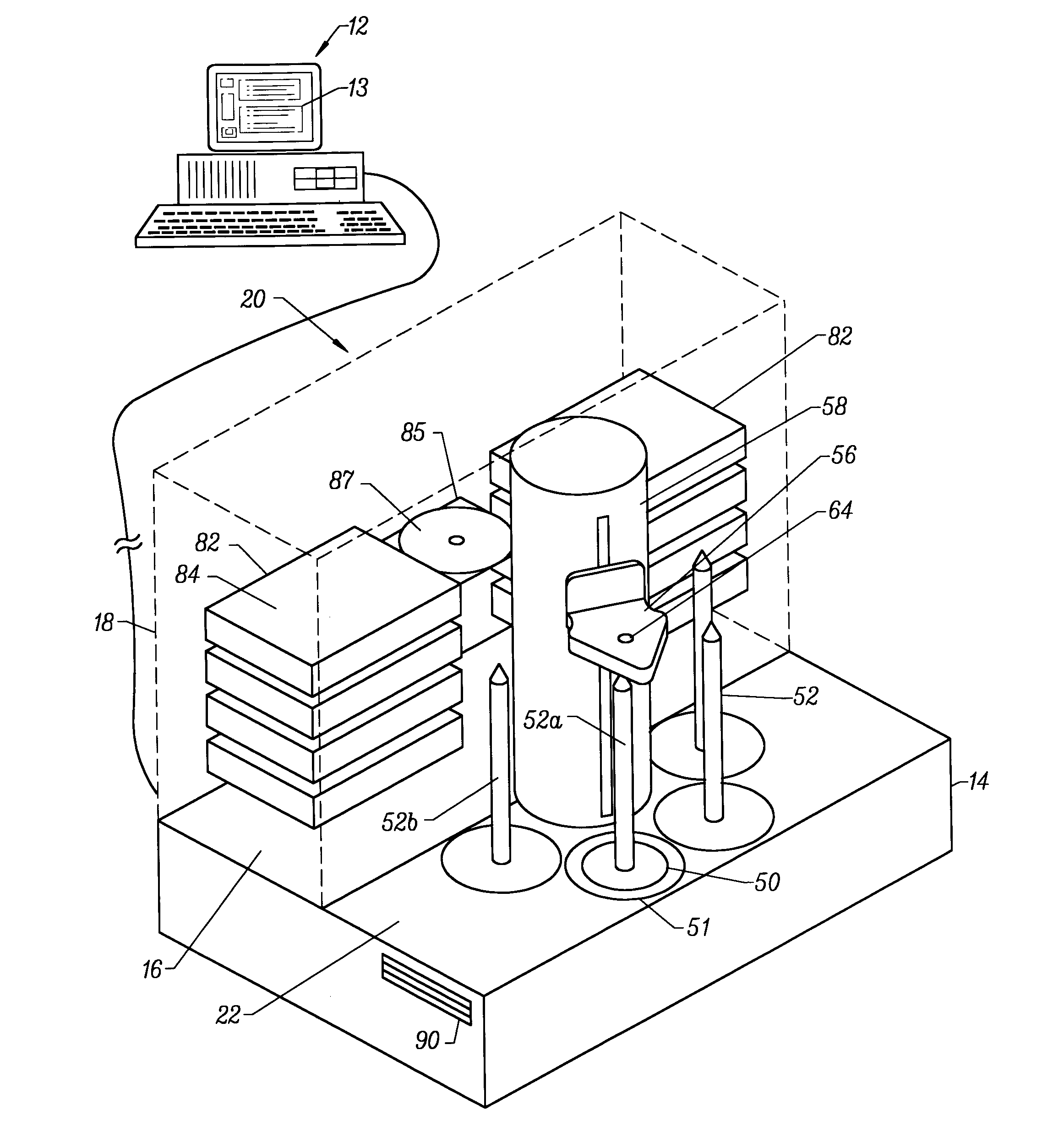
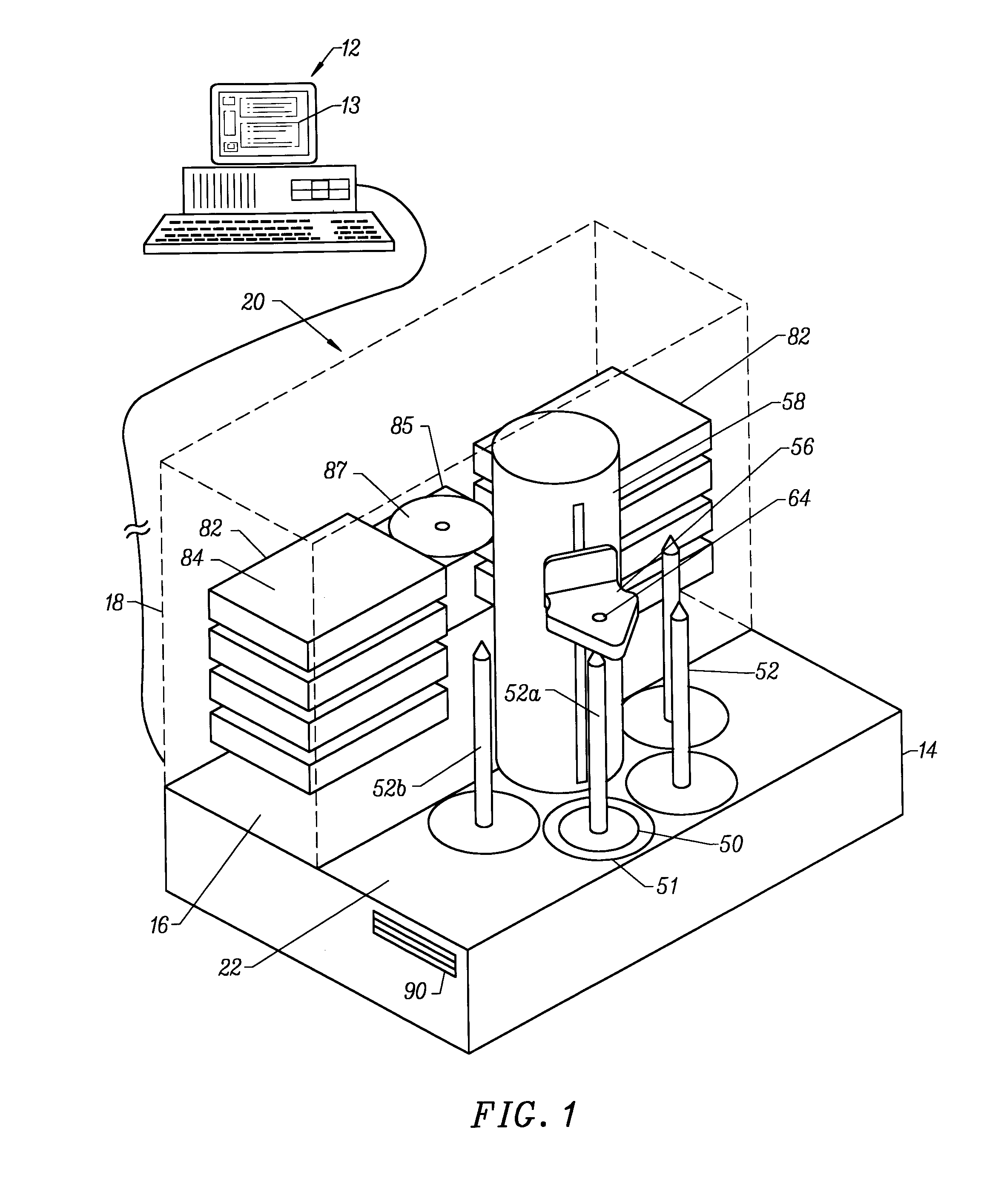
[0056]Referring to FIG. 1, the programmable automatic compact disk duplication system of this invention is designated generally by the reference numeral 10. The duplication system 10 includes a host computer 12, shown schematically, connected to a copy unit 20. The host computer 12 comprises a programmable computer that includes computer software for providing a user interface for operating the copying process of the copy unit 20. It is to be understood that the host computer may be incorporated into the copy unit 20 with the copy unit having a keyboard or other input device such as a control panel for managing the operation of the copy unit 20.

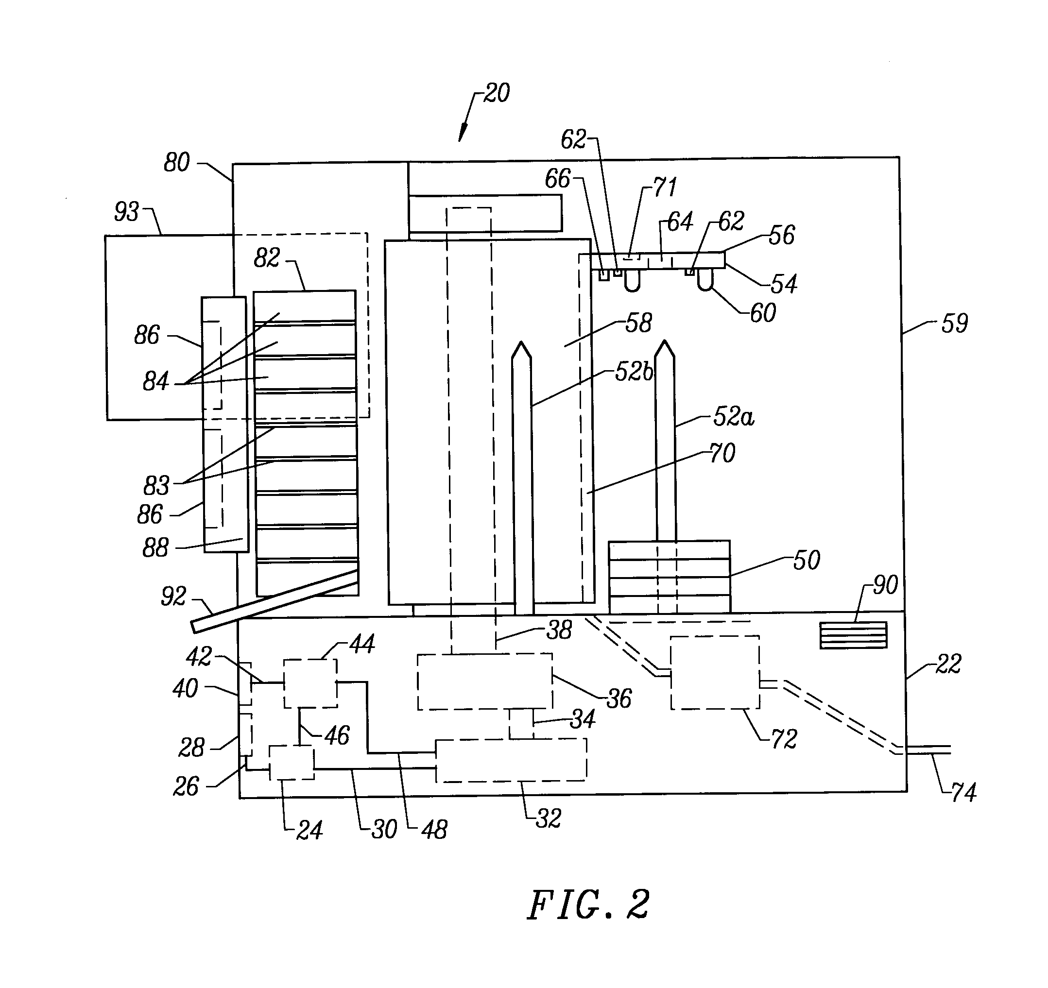
[0057]As shown in FIG. 2, the copy unit 20 includes an internal microprocessor 24 that is electrically connected to the host computer 12 for controlling the electromechanical operations of the copy unit 20. The copy unit 20 is constructed with a housing 14 having a deck 16 housing the electronics and drive assemblies, and a cabinet 18 housing...


PUM


Abstract

A system for the duplication of binary data onto CD-R disks, the system including a copy unit, a host computer and computer software, the software being installed in the host computer to provide a user interface and to direct the transfer of data from the host computer to the copy unit including a set of multiple stacked recordable disk drives, a microprocessor electronically connected to the activating mechanism of a pivotal transport tower and to the set of multiple stacked recordable disk drives. A robotic disk pickup head on the pivotal transport tower is encompassed by a set of disk spindle members arranged in a symmetric semi-circular pattern around the central tower, the disk pickup head being connected to the pivotal transport tower with an elevator mechanism for lifting and transporting compact disks among the disk spindle members and any selected one of the stacked recordable disk drive members.

Description

[0001]This application is a continuation of application Ser. No. 10 / 385,726, filed Mar. 10, 2003, now U.S. Pat. No. 6,822,932, which is a divisional of application Ser. No. 09 / 696,376, filed Oct. 25, 2000, now U.S. Pat. No. 6,532,198, which is a divisional of application Ser. No. 09 / 152,815, filed Sep. 14, 1998, now U.S. Pat. No. 6,141,298, which is a continuation-in-part of application Ser. No. 08 / 816,257, filed Mar. 13, 1997, now abandoned.BACKGROUND OF THE INVENTION[0002]Digital compact disks were originally conceived in the early 1980's as a technique to accurately copy and preserve audio recordings intended for sale to a mass market of consumers. As computing power has increased exponentially since that time, information processing tasks unthinkable only a few years ago have become commonplace and require large amounts of data most economically and conveniently stored on digital compact disks.[0003]Until recently the transfer of data onto compact digital disks was a costly proc...

Claims


Application Information

Patent Timeline
IPC IPC(8): G11B17/22
CPCG11B17/08G11B17/225
Inventor MILLER, DAVID
Owner MILLER DAVID
Why Eureka
Try Eureka