
Method for smooth trap suppression of small graphical objects

Inactive Publication Date: 2006-12-05
XEROX CORP
View PDF7 Cites 5 Cited by
  • Summary
  • Abstract
  • Description
  • Claims
  • Application Information

AI Technical Summary

Benefits of technology

[0008]The method of the invention can be used to reduce hue shifts in thin objects and small objects caused by trapping suppression in trap generators. A method for smooth trapping of a thin graphical object, according to one aspect of the invention, includes receiving from a trap generator the location of a trap pixel in a thin object that should be changed in color; wherein a thin graphical object has a width dimension which is substantially less than the object's length dimension, determining the width of the thin object containing the trap pixel; comparing the width of the thin object with a trap threshold width; if the width of the thin object is less than the trap threshold width, reducing the width of the trap region according to a predetermined relationship; and applying a trap correction to the trap pixel according to the reduced trap region width.
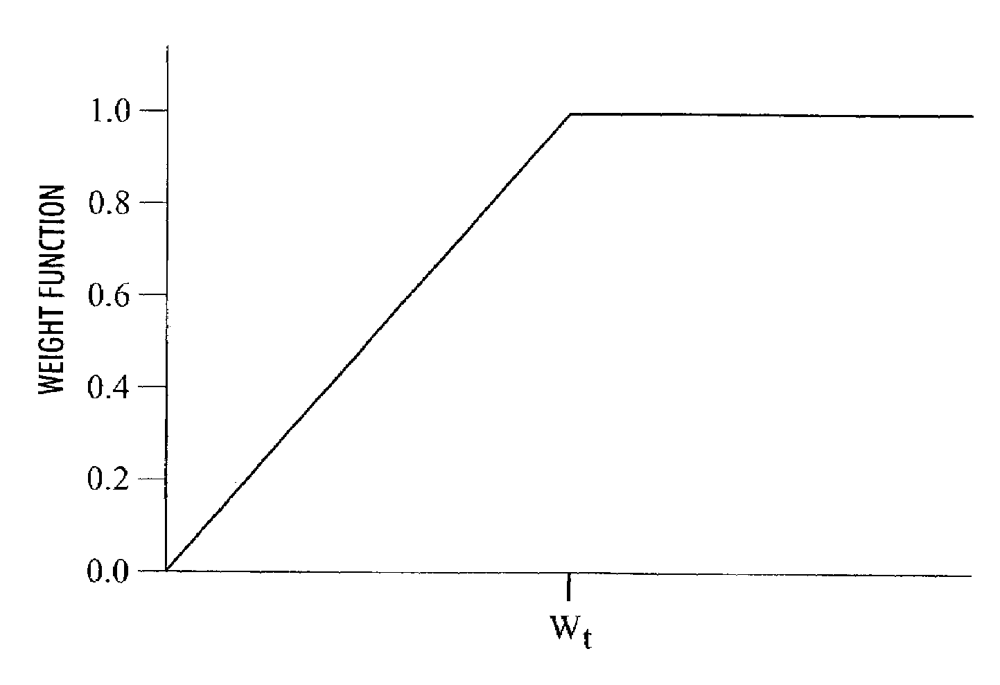
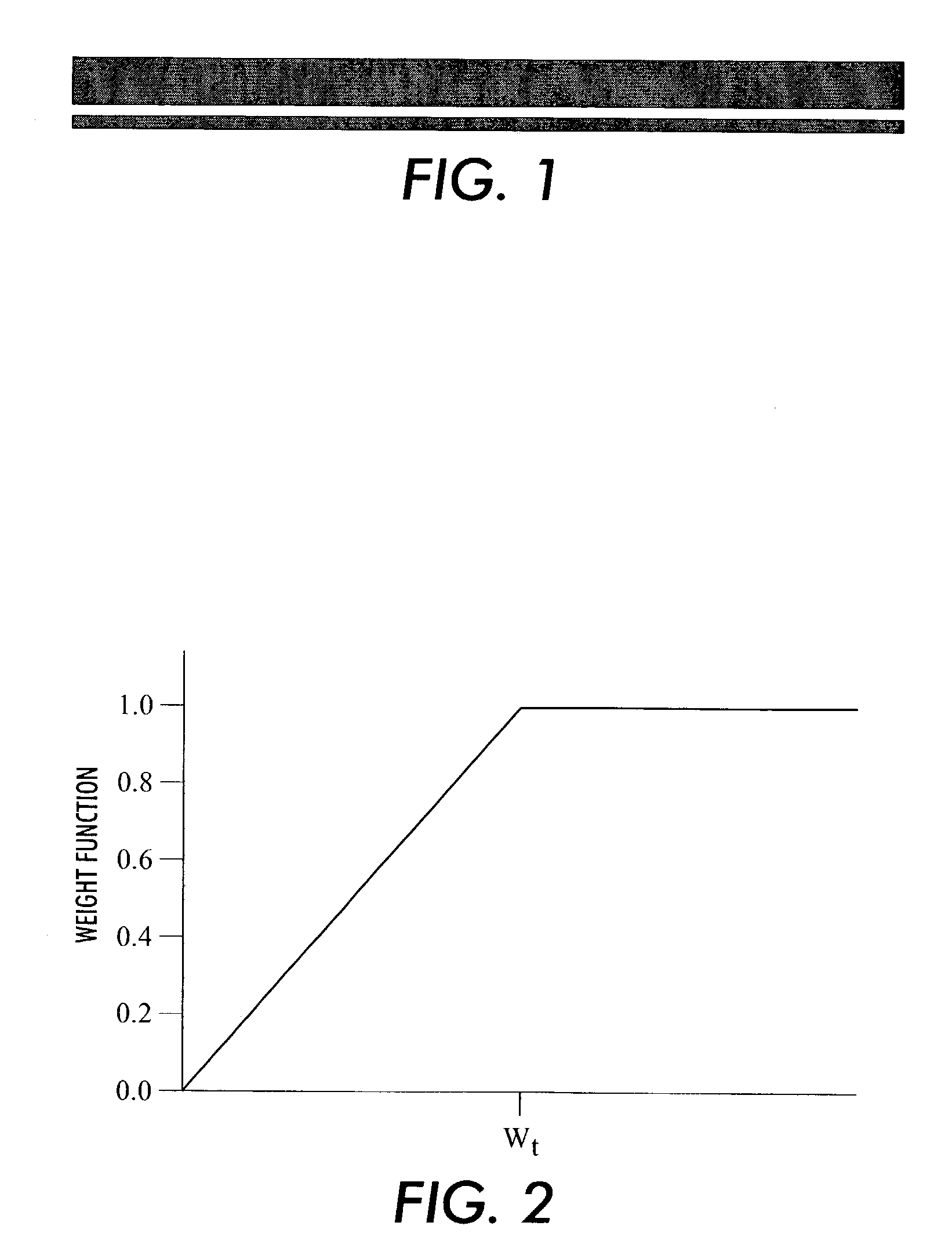
[0009]In one embodiment, the predetermined relationship may be a relationship which reduces the trap width monotonically. Instead of completely eliminating trapping for dimensions below a threshold, the method of the invention reduces the trap distance in a monotonic fashion (as the object size is reduced). As a result, the hue shift will be reduced, while preserving some degree of trapping at the edges to reduce visible misregistration errors.

Problems solved by technology

Typically, four process colors, cyan, magenta, yellow and black, are used to print multiple separations, which tend to have minor misregistration problems.
In practice, the realization of a zero width boundary between regions of different color is impossible as a result of small but visible misregistration problems from one printed separation to another.
The error is manifested as a “light leak” or as a visible boundary region of an undesired color.
For the typical trapping operation, it is assumed that objects to be trapped are very large relative to the trapping region, so that the trap colors will be difficult to distinguish.
However, for objects smaller than a few pixels, or for long, thin objects having a width less than a few pixels, trapping results in visible hue changes in the color of the entire object.
If the thin line, or the small object, happens to be located near a larger object of the same initial color, there will be a visible hue shift relative to the larger object, and the result of the trapping operation will be less desirable than no trapping at all.
This has the effect of eliminating the hue shift, but misregistration errors become visible once again.

Method used


Image

  • Method for smooth trap suppression of small graphical objects
  • Method for smooth trap suppression of small graphical objects

Examples


Embodiment Construction

[0016]One aspect of the method for smooth trap suppression of thin objects according to the invention involves determining how much to trap based on the size of the incoming page objects. Consider two different trapping scenarios, a thick and thin red line, as depicted in FIG. 1. In this example, most trap engines will reduce the yellow content at the edges of both objects to produce an optimal misregistration correction, resulting in a magenta-cast trap. If this trap is applied to the thicker line, the edge hue shift is almost imperceptible relative to the body of the line. However, the thin line below it shows a noticeable hue shift along the edge, since in that case the trap comprises a large fraction of the line area.

[0017]Many trapping algorithms completely disable trapping for objects whose dimensions fall below a specified trap width threshold. A drawback to this approach is the return of any misregistration errors that trapping would have reduced. The method of the invention...


PUM


Abstract

A method for smooth trapping of thin graphical objects, wherein a thin graphical object has a width dimension which is substantially less than the object's length dimension, includes receiving from a trap generator the location of a trap pixel that should be changed in color; determining the width of the object containing the trap pixel; comparing the width of the object with a trap threshold width; if the size of the object is less than the trap threshold width, reducing the width of the trap region according to a predetermined relationship; and applying a trap correction to the trap pixel according to the reduced trap width. The predetermined relationship may be a linear relationship which reduces the trap width monotonically for object widths less than the trap threshold width. The method may be applied to small objects and small font text objects.

Description

CROSS REFERENCE TO RELATED APPLICATIONS[0001]This invention is related to the inventor's application for “Method for Smooth Trap Suppression of Small Graphical Objects Using Run Length Encoded Data” which has been assigned to the assignee of this invention and which has been filed the same date as this application.FIELD OF THE INVENTION[0002]This invention relates generally to methods for correcting for marking engine characteristics, and more particularly, to a method smooth trapping suppression of small and thin graphical objects.BACKGROUND OF THE INVENTION[0003]Electronic processing of graphic and text images produces multi-color prints using multiple color separations. Typically, four process colors, cyan, magenta, yellow and black, are used to print multiple separations, which tend to have minor misregistration problems. The result of abutting or overlapping shapes is a boundary between adjacent regions of color that, under ideal printing conditions should have zero width. That...

Claims


Application Information

Patent Timeline
IPC IPC(8): G06K9/00G03F3/08G06K9/40G06T5/00G06T5/20
CPCG06T5/20
Inventor MCELVAIN, JON S.
Owner XEROX CORP
Learn More