Method of making an electric motor

a technology of electric motors and motors, applied in the field of dynamoelectric machines, can solve the problems of reduced slot volume of magnet wires, reduced efficiency, and reduced capital expenditur

Inactive Publication Date: 2006-12-12
BLACK & DECKER INC
View PDF357 Cites 25 Cited by
  • Summary
  • Abstract
  • Description
  • Claims
  • Application Information

AI Technical Summary

Problems solved by technology

First of all, it is a capital intensive process.
However, increasing the amount of magnet wires placed in the slots can cause the end ring to deform.
The end ring can be thickened to reinforce it, but this reduces the slot volume available for the magnet wires.
The process of applying the trickle resin is a somewhat difficult process to manage to obtain consistent results.
It also has a number of drawbacks, not the least of which is the cost and difficulty of performing it with reliable, consistent results.
Initially, the trickle process requires the use of a relatively large and expensive oven to carefully preheat the partially assembled stators to relatively precise temperatures before the trickle resin can be applied.
It has proven to be extremely difficult to achieve consistent, complete flow of the trickle resin through the slots in the lamination stack.
As such, it is difficult to achieve good flow between the magnet wires with the trickle resin.
Further complicating the manufacturing process is that the trickle resin typically has a short shelf life, and therefore must be used within a relatively short period of time.
The end result is that stators must often be designed for the process as opposed to optimum performance and cost.

Method used


Image

  • Method of making an electric motor
  • Method of making an electric motor
  • Method of making an electric motor

Examples


Embodiment Construction

[0040]The following description of the preferred embodiment(s) is merely exemplary in nature and is in no way intended to limit the invention, its application, or uses.

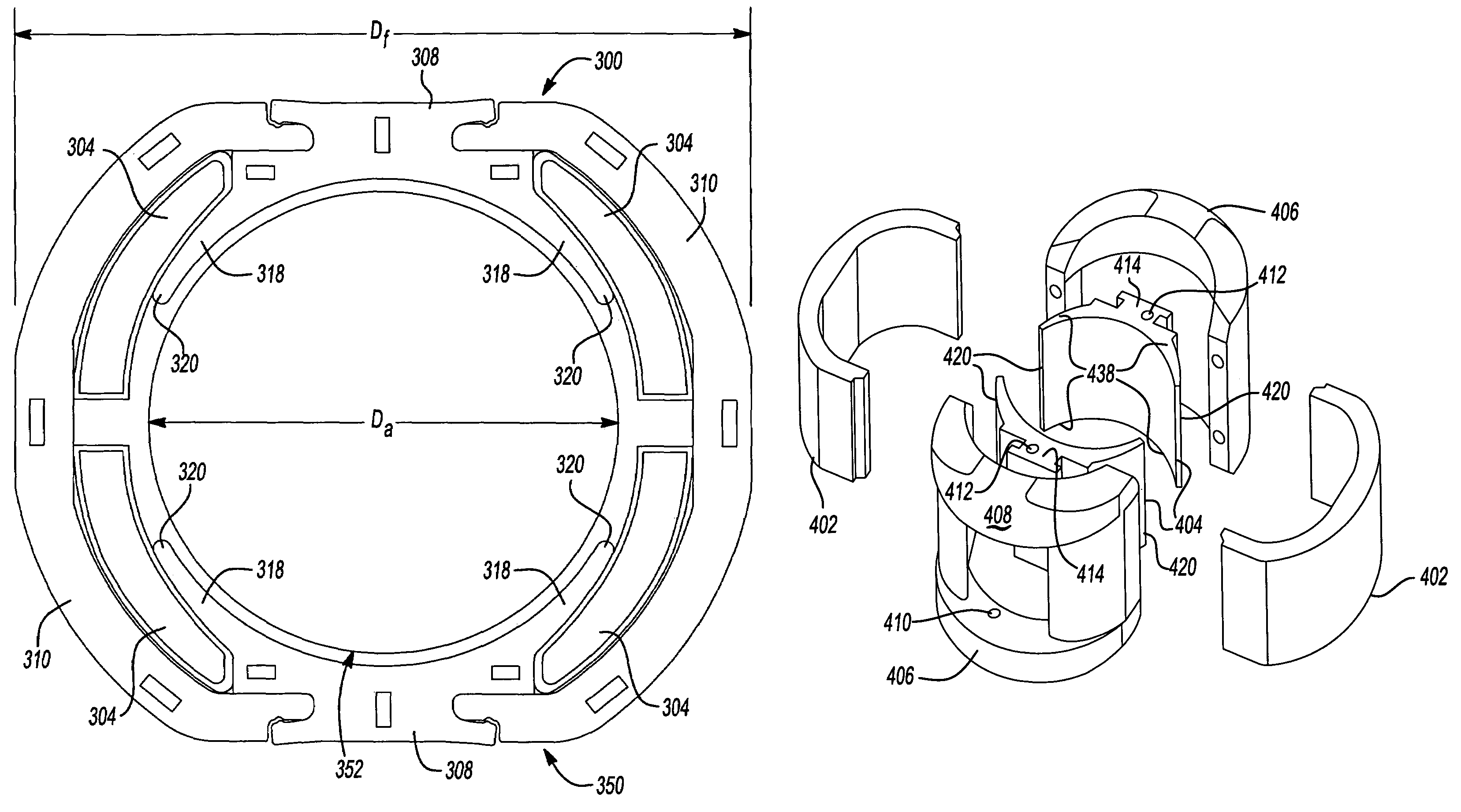
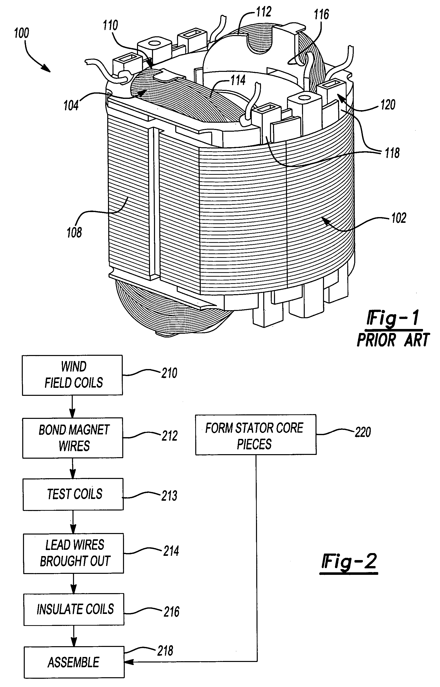
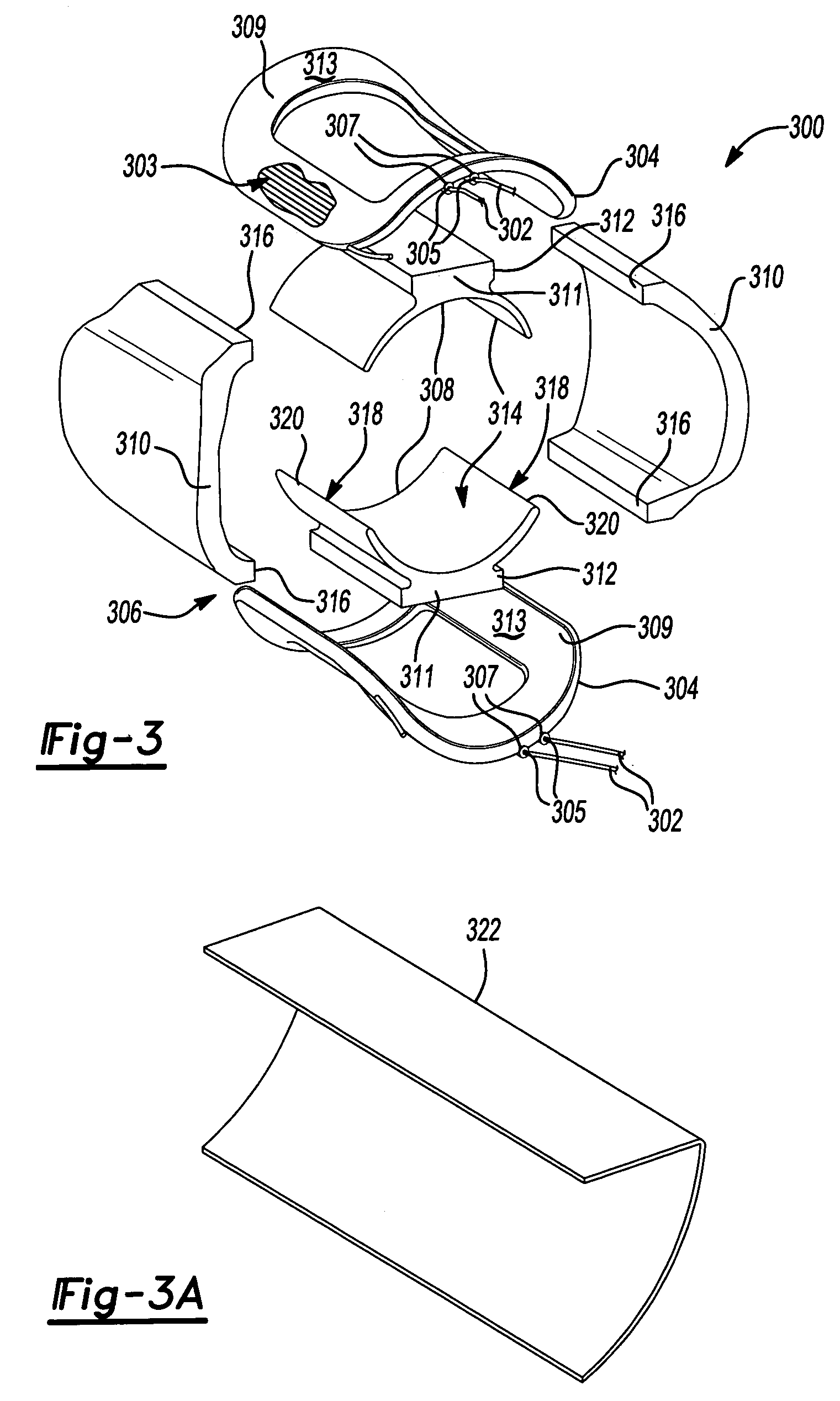
[0041]Referring to FIGS. 2 and 3, a process for making a field assembly, stator 300 in this instance, in accordance with an aspect of the invention is shown. At step 210, a coil, such as coil 614 (FIG. 6), for field coils 304 of stator 300 is wound to a predetermined shape, preferably net shape, by winding magnet wires 303 to the predetermined shape. “Net shape” means the final shape of the field coils 304 in an assembled stator 300. At step 212, the magnet wires 303 are bonded together. The magnet wires 303 are preferably bondable magnet wires, such as BONDEZE wires, having a layer of heat activated thermoplastic or thermoset adhesive thereon and heat is applied to the formed coil 614 to activate the adhesive on the magnet wires 303 to bond them together. It should be understood that the magnet wires can be bonded wh...


PUM

PropertyMeasurementUnit
cycle timeaaaaaaaaaa
diameteraaaaaaaaaa
diameteraaaaaaaaaa

Abstract

An electric motor has a field assembly, such as a stator, for a dynamoelectric machine has field coils that are wound to a net shape. Lead wires are brought out from the ends of each field coil. The field coils are insulated with insulating sleeves or insulating slot liners. The field coils are assembled with stator core pieces, such as pole pieces and return path pieces, into the stator. The stator core pieces are formed prior to being assembled with the field coils. In an aspect of the invention, the pole pieces and return path pieces are separately formed and then assembled together with the field coils, which have also been separately formed.

Description

CROSS-REFERENCE TO RELATED APPLICATIONS[0001]This application claims the benefit of U.S. Provisional Application No. 60 / 500,384, filed on Sep. 5, 2003, and Ser. No. 60 / 546,243 filed on Feb. 20, 2004. The disclosures of the above applications are incorporated herein by reference.FIELD OF THE INVENTION[0002]The present invention relates to dynamoelectric machines, and more particularly, to fields for dynamoelectric machines and methods of making them.BACKGROUND OF THE INVENTION[0003]Dynamoelectric machines are machines that generate electric power or use electric power. Common types of dynamoelectric machines are alternators, generators, and electric motors.[0004]Electric motors are used in a wide variety of applications involving power tools such as drills, saws, sanding and grinding devices, and yard tools such as edgers and trimmers, just to name a few such tools. These devices all make use of electric motors having an armature and a field, such as a stator.[0005]FIG. 1 shows a typ...

Claims


Application Information

Patent Timeline
Patent Type & Authority Patents(United States)
IPC IPC(8): H02K15/00H02K15/14H02K15/16H02K1/14H02K1/18H02K3/32H02K3/52H02K15/04H02K15/10H02K15/12
CPCH02K1/148H02K1/18H02K3/325H02K3/522H02K15/0435Y10T29/49073H02K15/12Y10T29/53143Y10T29/49012Y10T29/49009Y10T29/49071H02K15/10
Inventor DU, HUNG T.VERBRUGGE, BRANDON L.ORTT, EARL M.AGNES, MICHAEL J.ZEMLOK, MICHAEL A.KUSMIERSKI, ROBERT G.SMITH, DAVID J.
Owner BLACK & DECKER INC
Why Eureka
Try Eureka