Solenoid valve

a solenoid valve and valve body technology, applied in the field of valve assembly, can solve the problems of significant cost factor for electrical control of solenoid valves, relative high leakage flux, etc., and achieve the effect of convenient movemen

Active Publication Date: 2005-08-04
KARL DUNGS
View PDF11 Cites 64 Cited by
  • Summary
  • Abstract
  • Description
  • Claims
  • Application Information

AI Technical Summary

Benefits of technology

[0010] This objective is attained with the valve assembly according to Claim 1: The valve assembly according to the invention comprises two valve closing elements that can be moved into the open position by exciting a single magnetizing coil. One armature is respectively assigned to each valve closing element, with the two armatures preferably being arranged axially one behind another. An outer magnetic circuit with two pole pieces belongs to the magnetizing coil. The upper pole piece is assigned to the upper armature and the lower pole piece is assigned to the lower armature. A working air gap is formed between the two armatures. In addition, the upper armature forms a working air gap together with the upper pole piece. This measure ensures that upon excitation of the magnetizing coil, the ensuing magnetic flux flows through the two armatures in succession. This causes the two armatures not only to be pulled toward one another, but also to move upward, i.e., in the opening direction relative to the valve closing elements. The two valve closing elements are able to close independently of one another if the excitation ceases. Should the upper armature become stuck in the open position, the lower (inner) armature can still be moved into the closed position. If the lower (inner) armature becomes stuck, the upper armature and its closing element can be easily moved into the closed position.
[0011] Since the special design of the magnetic circuit ensures a serial flux through both armatures, the magnetic flux generated by the coil is well utilized. Only relatively low currents are required for controlling and for holding the valves in the open position. The magnetic circuit only causes a low leakage flux. The working air gap defined between the first (upper) armature and the first (upper) pole piece can assume a minimal gap width with low leakage flux in the excited position. This applies analogously to the coupling air gap formed between the armatures. Consequently, it is possible to operate the valve with an electric and magnetic excitation that is no more intense than that for a single valve.
[0013] If the connecting sleeve or pipe section between the outer valve closing element and the first armature consists of a non-magnetic material that differs from the material of the first armature, it is necessary to mechanically produce a suitable gas-tight connection between the pipe section or sleeve and the first armature. The connection may be produced, for example, by means of laser welding, electron beam welding, bonding, screws, flanging or the like. A flanged connection that is utilized in connection with a corresponding elastomeric gasket, e.g., an O-ring, can be easily and inexpensively produced.
[0014] If the connecting sleeve consists of armature material, i.e., magnetic material, it is advantageous for the armature and sleeve to be integrally connected to one another such that no leakage problems occur.
[0015] The sleeve extends through the transmission air gap formed between the second pole piece and the second armature, with this transmission air gap preferably being longer in the axial direction than the axial travel of the second armature. This prevents forces that axially move the armature from being generated in the transmission air gap. However, the transmission air gap may also be utilized for boosting the armature actuation. This is achieved with a design, in which the second armature protrudes from the corresponding pole piece when the associated valve closing element is seated on its valve seat. This design causes the transmission air gap to increase when the corresponding valve is opened.

Problems solved by technology

Although this arrangement makes it possible to easily control two valve closing elements with a single coil, it causes a relatively high leakage flux because the non-magnetic sleeve completely surrounds the inner armature.
The electrical control of solenoid valves is a significant cost factor.

Method used


Image

  • Solenoid valve
  • Solenoid valve
  • Solenoid valve

Examples


Embodiment Construction

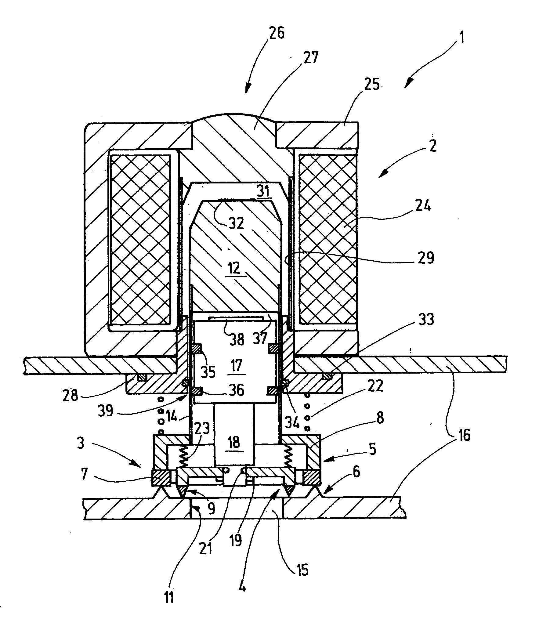
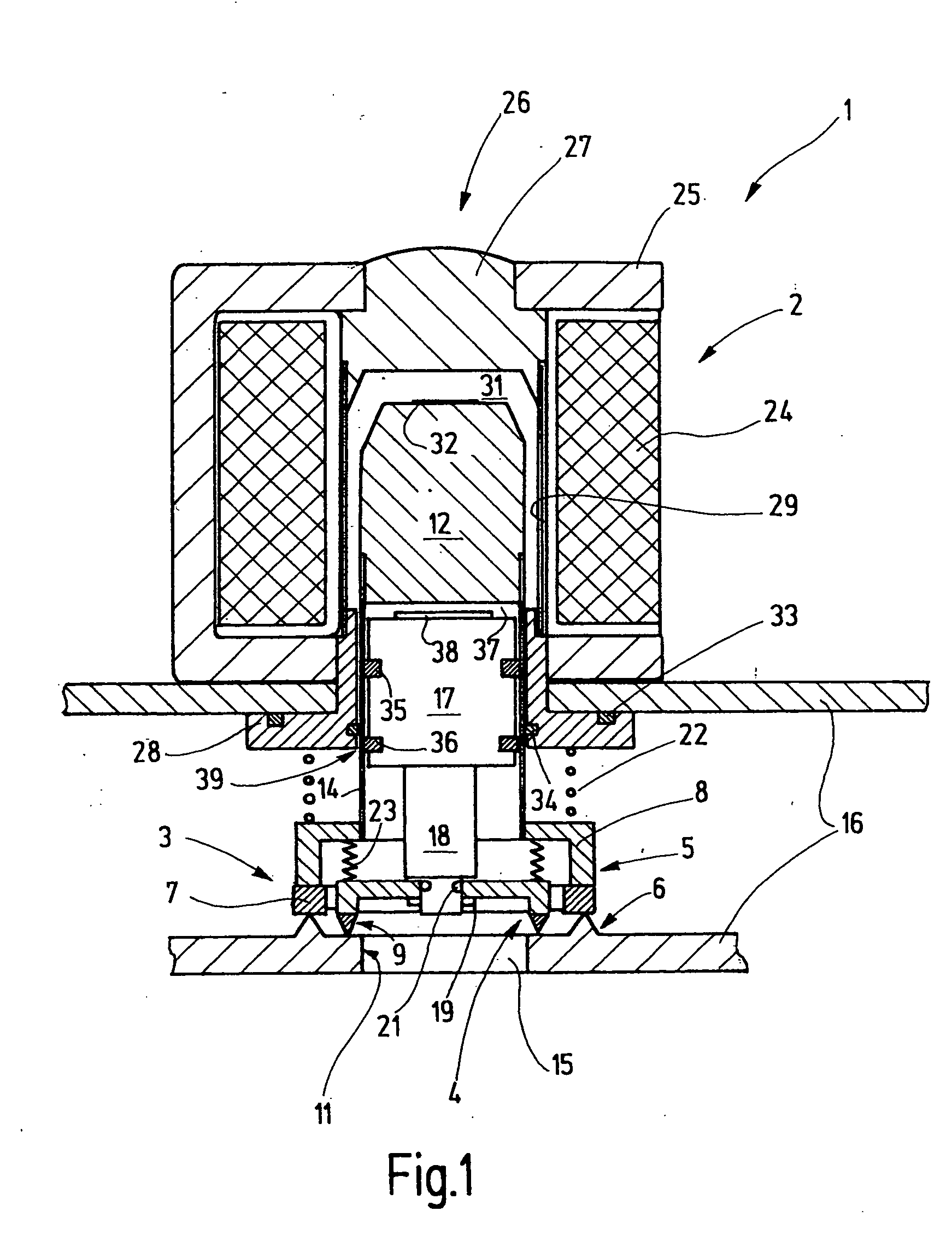
[0026]FIG. 1 shows a valve assembly 1 that comprises a solenoid actuator 2 and two valves 3, 4. The valve 3 is formed by a valve closing element 5 and a valve seat 6. The valve closing element 5 contains an annular sealing member 7, made of an elastomer, for example that is held on an annular face of a hollow-cylindrical body 8 that is closed on the top and has approximately the shape of a cup or bell.

[0027] The valve 4 comprises a valve closing element 9 and a valve seat 11. The valve seats 6, 11 may be structurally combined with one another, as shown in FIG. 1. This can be achieved, for example, by realizing the valve seat 6 in the form of an annular rib that concentrically surrounds the valve seat 11 realized in the form of a planar annular surface. However, it would also be possible to arrange the two valve seats 6, 11 separately from one another in the same plane or in different planes, but in both instances they are preferably arranged coaxial to one another.

[0028] A first a...


PUM


Abstract

A valve assembly comprises two valves and a single solenoid actuator with only one magnetizing coil that controls both valves. The corresponding magnetic circuit comprises a yoke with only two pole pieces. The valves are arranged concentric to one another. The valve closing element of the outer valve is connected to an armature by means of a sleeve. The cup thus formed receives the armature that is connected to the valve closing element of the inner valve. The pole piece and the armature form a transmission air gap through which the sleeve extends. A coupling air gap is formed between the armatures. The armature and the pole piece form a working air gap. The valves are opened collectively and are able to close independently of one another when the coil is rendered currentless.

Description

CROSS REFERENCE TO RELATED APPLICATIONS [0001] This application claims priority to German Application No. 10 2004 004 708.1 filed Jan. 30, 2004, which is incorporated herein by reference. TECHNICAL FIELD OF THE INVENTION [0002] The invention pertains to a valve assembly, in particular, for safety-relevant gas applications. BACKGROUND OF THE INVENTION [0003] In gas-operated devices, it is frequently required to utilize valves that are electrically opened and reliably close in the currentless state. In order to achieve the desired protection against malfunctions of valve components, two valves are usually arranged one behind another in the gas flow, with the two valves opening and closing independently of one another. If one of the valves becomes stuck in the open position, the second valve is still able to close and shut off the valve assembly, i.e., it is ensured that the valve assembly is closed. [0004] There also exists double-seat valve assemblies, in which both valves and the co...

Claims


Application Information

Patent Timeline
Patent Type & Authority Applications(United States)
IPC IPC(8): F16K1/44F16K31/06F23K5/00F23N1/00
CPCF16K1/443F16K31/0655H01F2007/1661F23N1/005F23N2035/14F23K5/007Y10T137/88038Y10T137/8704Y10T137/86928Y10T137/86984F23N2235/14
Inventor BERGER, SIEGFRIEDFORSTER, JOACHIM
Owner KARL DUNGS
Why Eureka
Try Eureka