Valve structure, bladder, and hull portion for inflatable boats

a valve structure and inflatable boat technology, applied in the field of valve structure and valve structure/bladder combination, can solve the problems of difficult formation of dividers, difficult deflating of entire collars, and inability to meet the needs of specialized materials and assembly techniques, and achieve the effects of easy deformation, and improved flexibility and elasticity

Active Publication Date: 2006-12-12
CRYOGENIC PLASTICS
View PDF22 Cites 18 Cited by
  • Summary
  • Abstract
  • Description
  • Claims
  • Application Information

AI Technical Summary

Benefits of technology

[0008]In accordance with one aspect of the invention, the valve structure made up of the valve body and the fill and pressure relief valves is incorporated with a bladder made of a flexible and elastic material. The valve body is positioned in a valve receiving opening in the bladder material and is sealed to the bladder material around the periphery of the valve receiving opening so as to define a sealed bladder interior with the bladder material. The lower or inner flange of the double flange structure may be used to provide an extensive surface for providing a durable seal between the valve structure and bladder material.
[0010]An inflatable hull portion according to the present invention uses the bladder to receive and retain inflation gas pressure for the hull portion, and uses the hull tube material for providing a tough and durable exterior surface. This allows the hull tube material to be selected without regard to its ability to hold gas pressure. The bladder material may be selected solely for its gas pressure holding properties and for its relatively greater flexibility and elasticity as compared to the hull tube material. Although the flexible bladder must be inserted into the hull tube, the hull tube access opening provides ready access for bladder insertion and also cooperates with the valve structure to retain the valve structure at the desired location to provide easy access to the fill and pressure relief valves or valve.

Problems solved by technology

A problem with current RIB boat collars is that specialized materials and assembly techniques are required to produce collars that are capable of retaining gas pressure and providing the desired durable exterior surface.
Another problem with current RIB boat collars is that a single puncture to the collar material will allow the entire collar to deflate unless air-tight dividers are used within the collar to form separate pressure cells along the length of the collar.
Although such dividers do solve the problem of having the entire collar deflate in response to a single puncture, the dividers are difficult to form.

Method used


Image

  • Valve structure, bladder, and hull portion for inflatable boats
  • Valve structure, bladder, and hull portion for inflatable boats
  • Valve structure, bladder, and hull portion for inflatable boats

Examples


Embodiment Construction

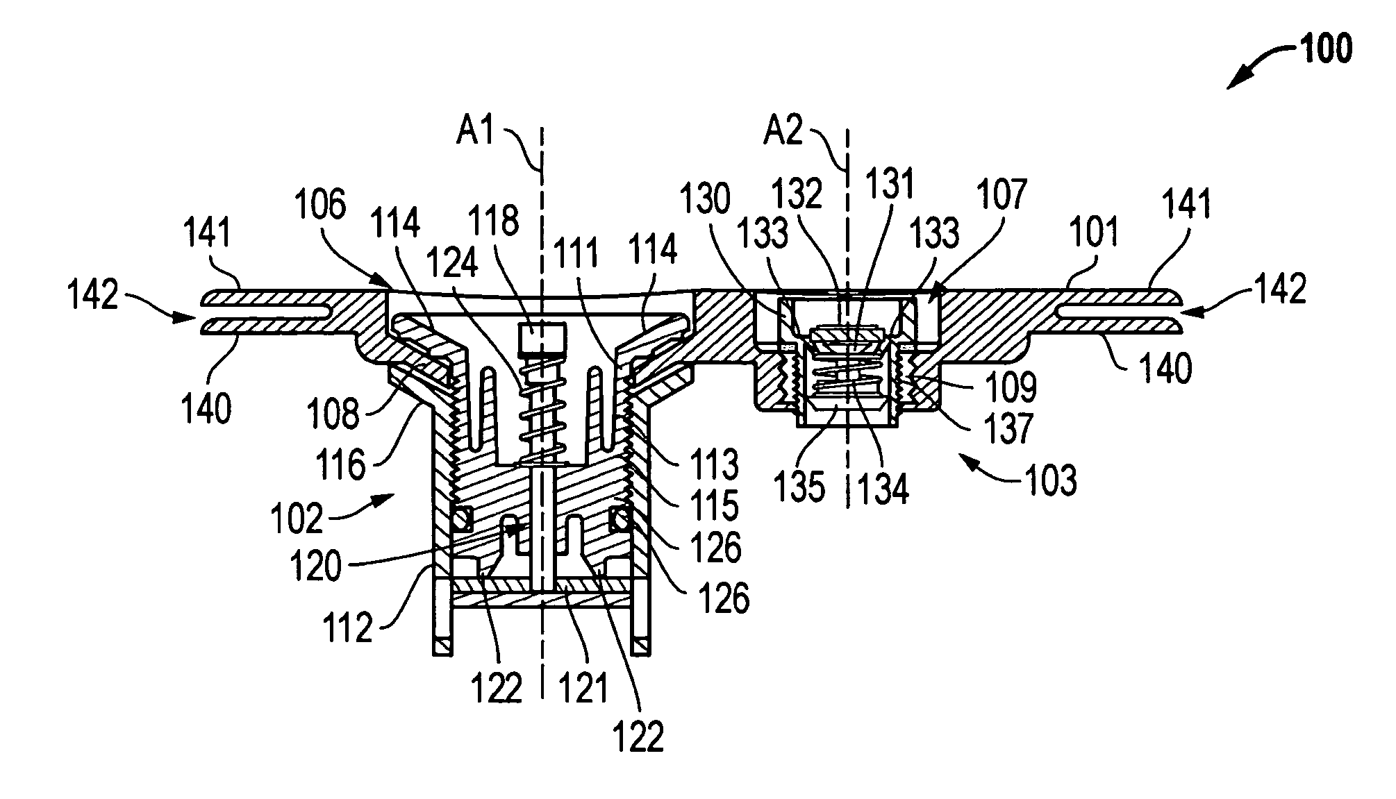
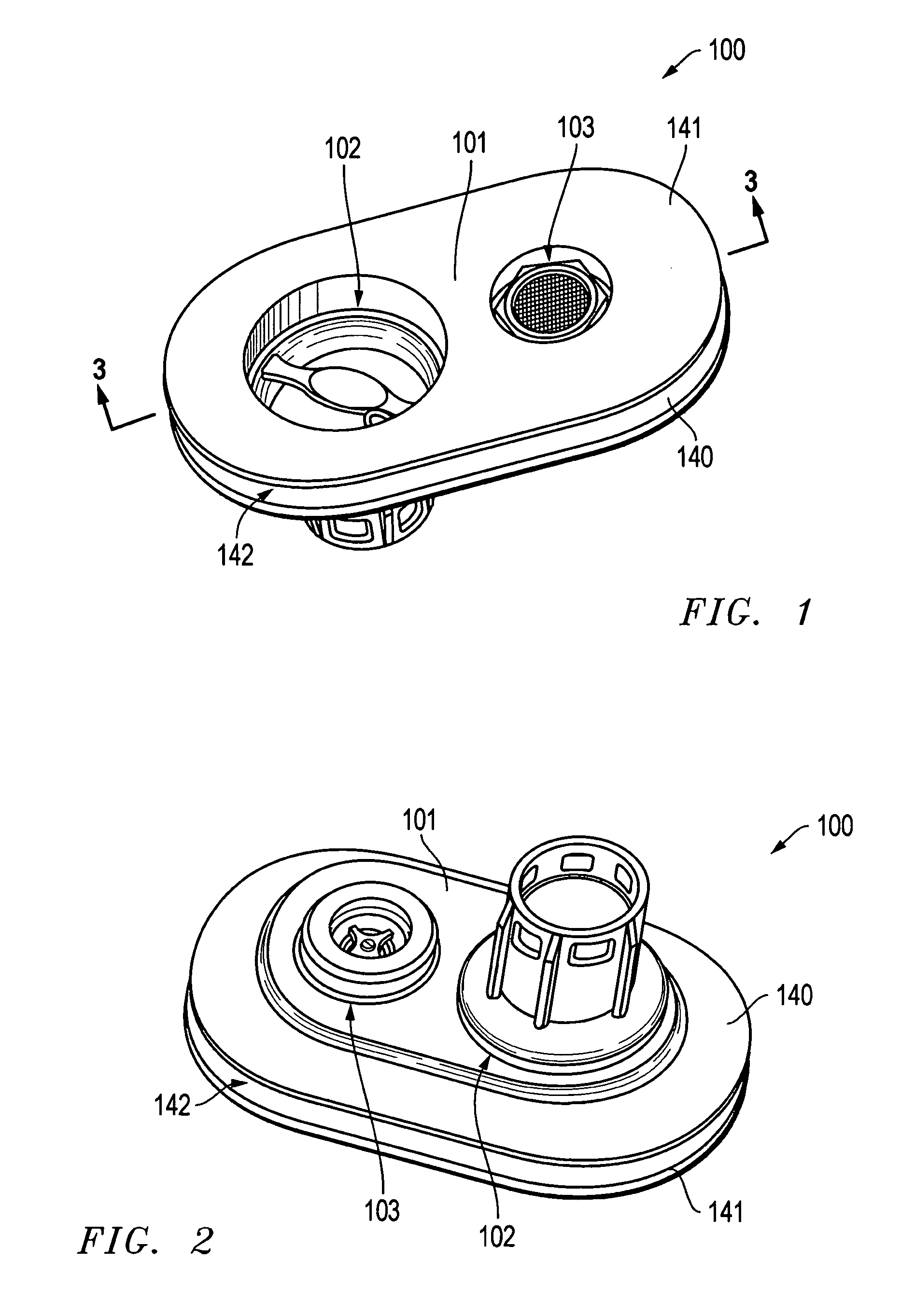
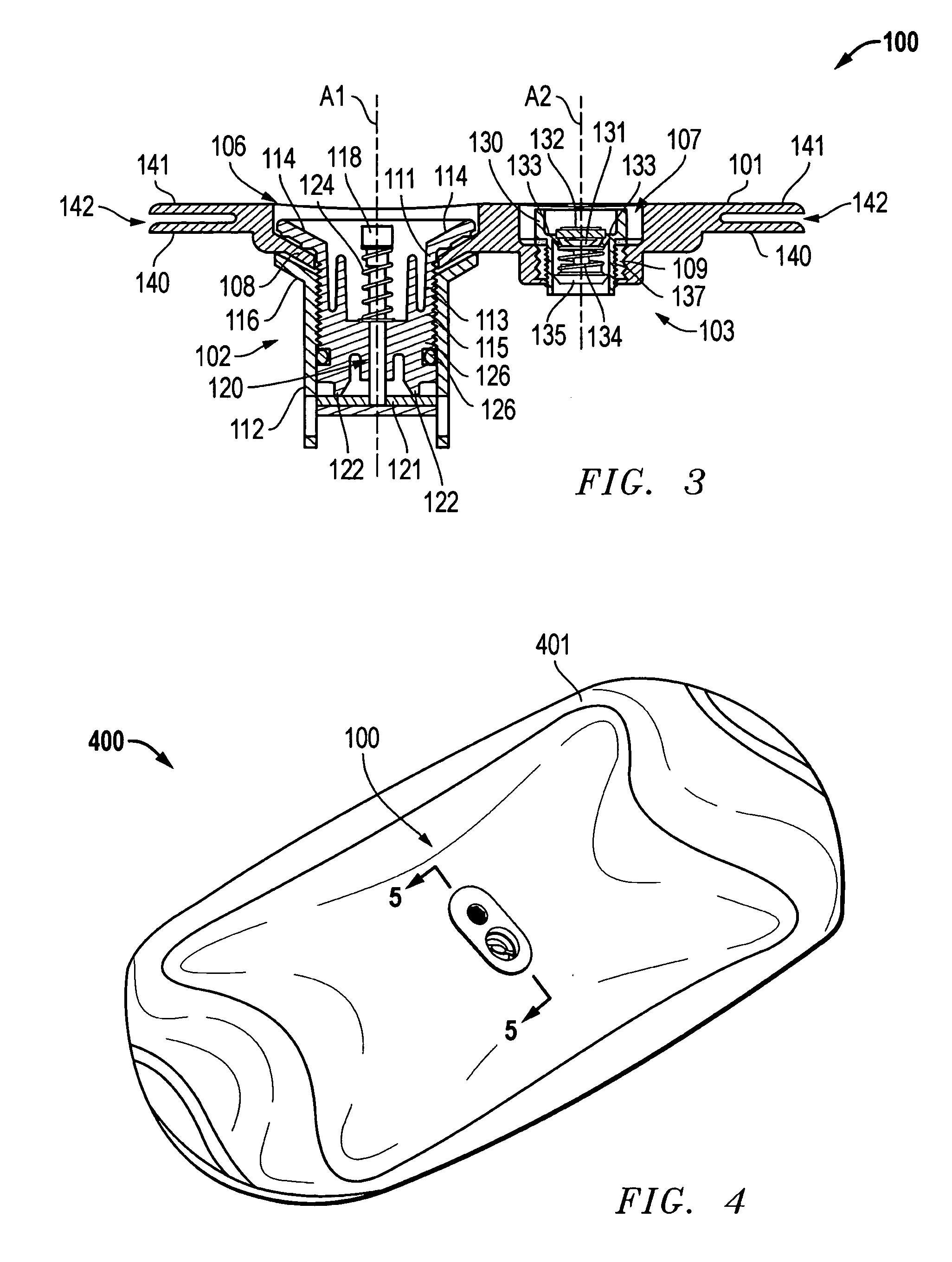
[0024]FIGS. 1 through 3 show a valve structure 100 for use in boats having an inflatable hull portion. Valve structure 100 includes a valve body 101, a first valve 102 traversing the valve body at a first position, and a second valve 103 traversing the valve body at a second position spaced apart from the first position.

[0025]As shown in FIG. 3, valve body 101 includes a first opening 106 for receiving first valve 102 and a second opening 107 for receiving second valve 103. First opening 106 includes a flange portion 108 to which first valve 102 is secured. Second opening 107 includes a threaded insert 109 in for receiving second valve 103.

[0026]The illustrated preferred first valve 102 is a fill valve (also called a topping valve) that allows air or other gas or fluid to be pumped into a bladder as will be described further below. As shown in FIG. 3, this preferred first valve 102 includes a top portion 111 and a bottom portion 112. Top portion 111 includes a threaded section 113 a...


PUM


Abstract

A valve structure includes a valve body on which is mounted a first valve and a second valve. The first valve traverses the valve body at a first position and the second valve traverses the valve body at a second position spaced apart from the first position. The first valve may comprise a fill valve and the second valve may comprise a pressure relief valve. Alternatively, a single valve structure may incorporate both the fill and pressure relief functions. The valve structure may be incorporated with a bladder made of a flexible and elastic material. In this arrangement, the valve body is positioned in a valve receiving opening in the bladder material and is sealed to the bladder material around the periphery of the valve receiving opening so as to define a sealed bladder interior with the bladder material. Such a valve and bladder combination may be used together with a hull tube to form a portion of an inflatable hull for a boat.

Description

CROSS-REFERENCE TO RELATED APPLICATION[0001]This application is related to U.S. provisional patent application No. 60 / 557,567, filed Mar. 30, 2004, entitled “Valve Structure, Bladder, and Hull Portion for Inflatable Boats,” the entire content of which is hereby incorporated herein by this reference. The Applicant hereby claims the benefit of this provisional application under 35 U.S.C. §119(e).TECHNICAL FIELD OF THE INVENTION[0002]The invention relates to a valve structure and valve structure / bladder combination for use in inflatable boats such as rigid inflatable boats and inflatable rafts. The invention also encompasses a hull portion or hull for such inflatable boats and rafts.BACKGROUND OF THE INVENTION[0003]Small boats and rafts have commonly used inflatable elements for buoyancy and for other purposes. Rafts using inflatable elements may include no rigid structure and rely on the inflatable elements to form a desired hull shape. Other boats include both a rigid hull and an inf...

Claims


Application Information

Patent Timeline
Patent Type & Authority Patents(United States)
IPC IPC(8): B63B7/00B63B7/08F16K31/53
CPCB63B7/00B63B7/08B63C9/24F16K31/53Y10T137/3584F16K15/207
Inventor POLLEY, DALEHOTZ, DAVIDTAYLOR, RUSSELL
Owner CRYOGENIC PLASTICS
Why Eureka
Try Eureka