One way clutch

a one-way clutch and clutch technology, applied in the direction of clutches, friction clutches, freewheel clutches, etc., can solve the problems of increasing costs, reducing the overall width (the dimension in the axial direction), and the mechanism for positioning must be additionally disposed, so as to achieve the effect of simple shape, reduced number of assembly steps, and reduced cos

Inactive Publication Date: 2006-12-12
KOYO SEIKO CO LTD
View PDF12 Cites 9 Cited by
  • Summary
  • Abstract
  • Description
  • Claims
  • Application Information

AI Technical Summary

Benefits of technology

[0016]As another mode of the urging means which is used in the invention, a spring may be used which is configured by an annular wire member, and which generates a spring force in a diameter reducing direction, and a configuration, according to an eighth aspect of the invention, may be employed in which the spring is placed to circumscribe the balls, thereby urging the balls in a direction along which the distance between the cam surface and the ball raceway surface is reduced.
[0036]In a one-way clutch in which rotation and stopping are repeated, an impact force is repeatedly applied to parts. Therefore, there is the possibility that parts of a small size and a complex shape are quickly damaged because of fatigue or the like. Since springs of a complex shape are not used, however, also the durability and the damage resistance are improved.

Problems solved by technology

In such a roller clutch, because of process restrictions or the like, the rollers 12 must have a length of a certain degree or more, and hence the reduction of the overall width (the dimension in the axial direction) is inevitably limited.
This is a cause of an increased cost.
Therefore, there is a further problem in that a mechanism for positioning must be additionally disposed.

Method used


Image

  • One way clutch
  • One way clutch
  • One way clutch

Examples


Embodiment Construction

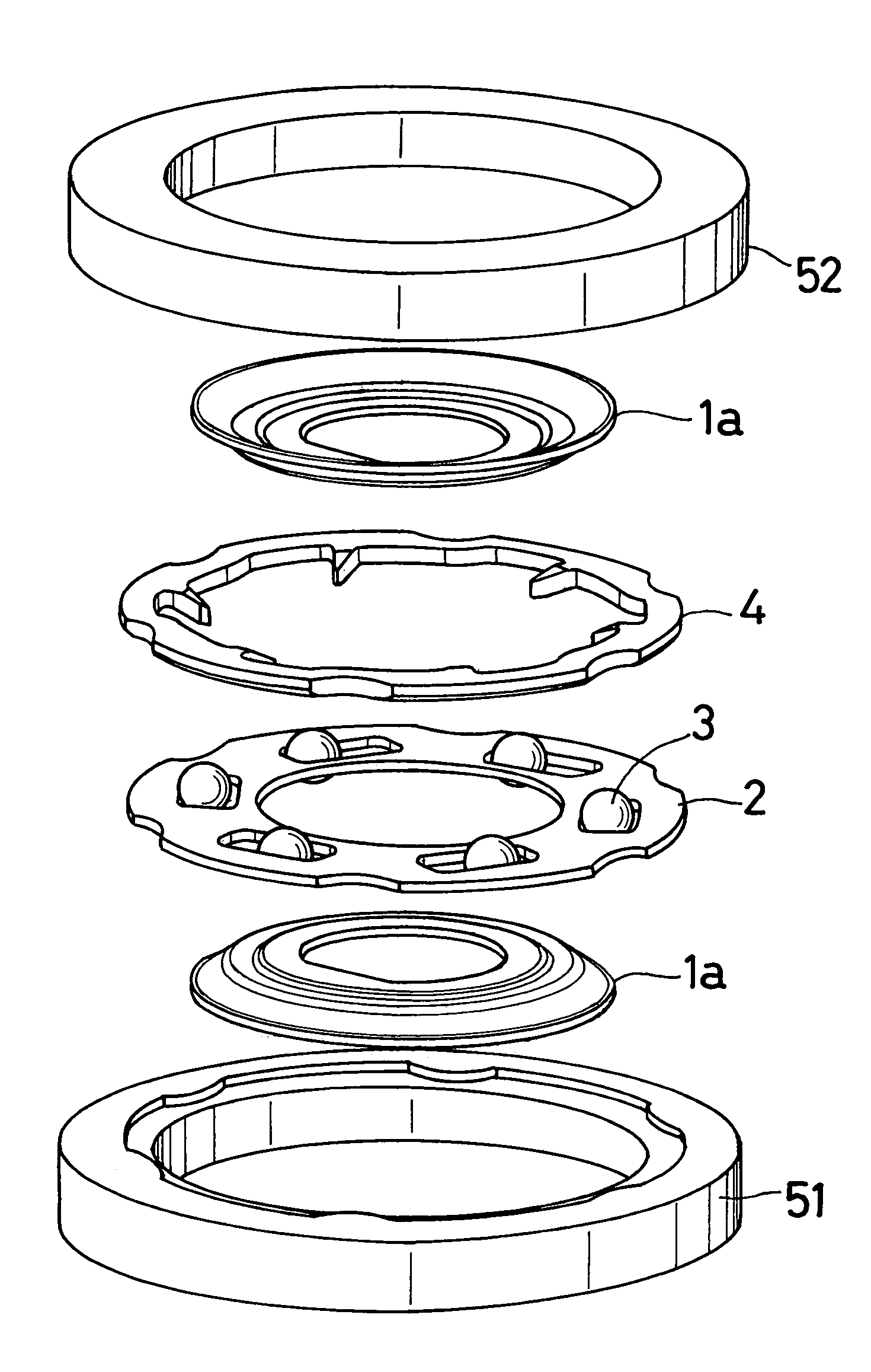
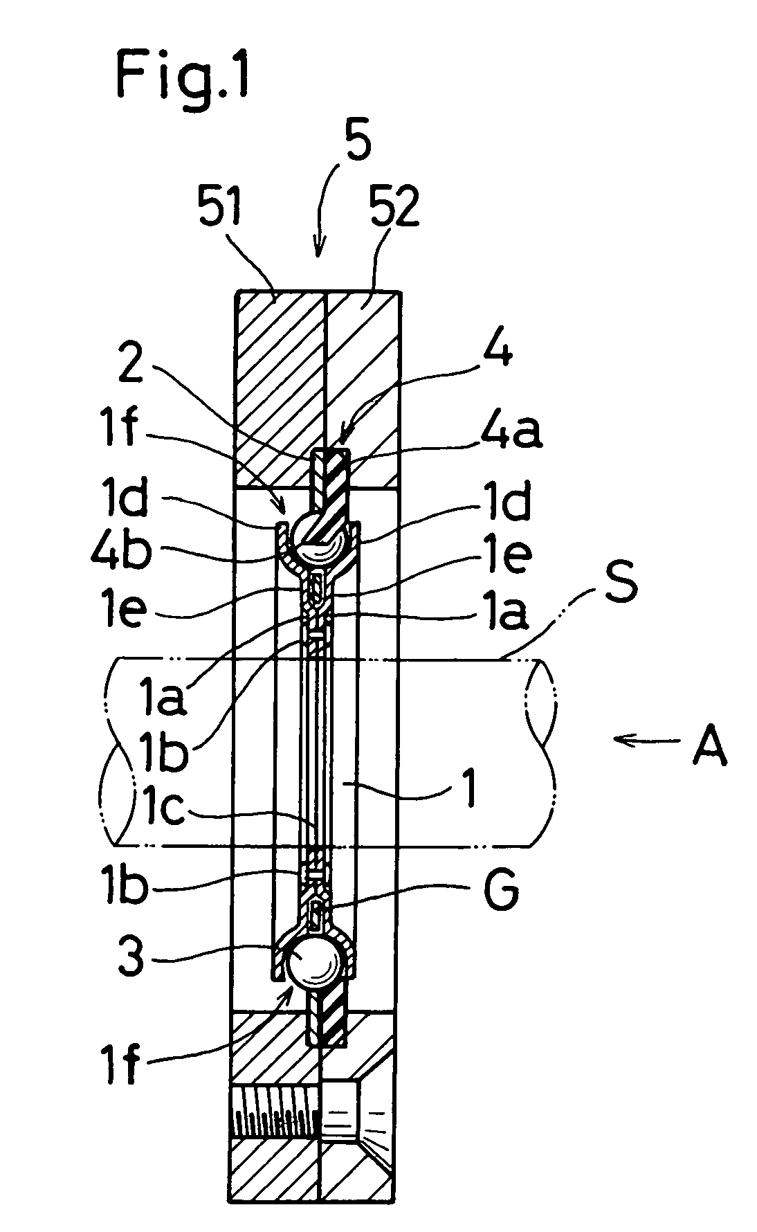
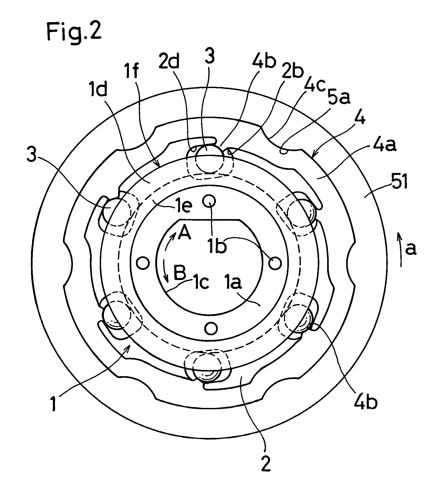
[0065]An embodiment shown in FIGS. 1 to 6 is configured by an inner race 1, an outer race 2, balls 3, a spring 4, and a housing 5.

[0066]In the inner race 1, as shown in FIG. 4, two inner race plates 1a, 1a which are formed by, for example, applying punching press molding on a plate member such as a stainless steel plate overlay each other and are then fixed to each other by rivets 1b, and the inner face 1c has a D-cut shape so that, when the inner race is fixed to a shaft S, a large torque can be loaded. Curved portions 1d are formed in outer edges of the inner race plates 1a, 1a, and step portions 1e are formed on the inner peripheral side of the plates in order to form an air gap G between the inner race plates 1a, 1a in the overlaying state. As shown in FIGS. 1 and 2, a raceway surface 1f for the balls 3 is formed by curved portions 1d, 1d of the two inner race plates 1a, 1a, and the outer race 2 is inserted into the air gap G.

[0067]In the embodiment, the two inner race plates 1a...


PUM


Abstract

A one-way clutch includes an outer race, wherein a plurality of windows are formed in one plate-like member, is placed so as to be relatively rotatable with respect to an inner race wherein two plate-like members overlay each other and a ball raceway surface is formed by curved portions formed in outer peripheries of the plate-like members. Balls are accommodated in the windows. The face of each of the windows on the side of the outer periphery of the outer race is formed as a cam surface wherein the distance with respect to the ball raceway surface is reduced in a circumferential direction. Urging means for urging the balls in the direction is disposed. The maximum width of the one-way clutch is equal to the ball diameter and the thicknesses of the two plate-like members constituting the inner race, so that a one-way clutch of a reduced width is obtained.

Description

BACKGROUND OF THE INVENTION[0001]The present invention relates to a one-way clutch, and more particularly to a compact one-way clutch which has a reduced width.[0002]As a one-way clutch which transmits relative rotation between a shaft and a housing in one direction, and which runs idle in the other direction, known is a roller clutch which is shown in a section view taken parallel to the axis of FIG. 23, and a section view taken perpendicular to the axis of FIG. 24. Such a roller clutch is often used in a reel of a fishing gear, a sheet feeding mechanism of a copying machine, and the like.[0003]The roller clutch is configured by: an outer race 10; a shaft 11 which functions also as an inner race; a plurality of rollers 12 which are interposed between the outer race 10 and the shaft 11; a cage 13 which retains the rollers 12 at constant intervals in the circumferential direction; and springs 14 which urge the rollers 12 in respective constant directions. Flanges 10a are formed on th...

Claims


Application Information

Patent Timeline
Patent Type & Authority Patents(United States)
IPC IPC(8): F16D41/06F16D41/067
CPCF16D41/067
Inventor IGA, KAZUOSAKAMOTO, KENJITANIMOTO, KIYOSHI
Owner KOYO SEIKO CO LTD
Why Eureka
Try Eureka