Pupilometer with pupil irregularity detection, pupil tracking, and pupil response detection capability, glaucoma screening capability, intracranial pressure detection capability, and ocular aberration measurement capability

a pupil irregularity and pupil tracking technology, applied in the field of pupil irregularity detection, can solve the problems of inaccuracy and human/patient error, affecting the diagnosis accuracy, and difficulty in positioning an imager,

Inactive Publication Date: 2006-12-12
NEUROPTICS
View PDF70 Cites 20 Cited by
  • Summary
  • Abstract
  • Description
  • Claims
  • Application Information

AI Technical Summary

Benefits of technology

[0029]In another innovative aspect, the present invention is directed to a medical diagnostics system incorporating a pupilometer for testing the functional integrity of auditory pathways, and for methods of implementing and utilizing such a system. The system comprises a pupilometer for obtaining data descriptive of one or more pupilary characteristics of an eye of a patient, as described herein. The system further comprises a sound generating transducer in connection with an ear-piece, wherein the transducer is synchronized to the pupilometer such that images of the eye are captured by the pupilometer in sequence with the generation of sound. Thus, hearing can be tested in a quantifiable and objective manner by analyzing pupilary response rather than relying on the patient to consciously respond to the stimulus.

Problems solved by technology

The reason for this is that medical personnel at, for example, an accident site may have difficulty in positioning an imager in a prescribed position for acquiring pupilary response data.
The current standard of care for Glaucoma detection, however, suffers form inaccuracy and human / patient error.
Thus, if the patient is not concentrating or responds too quickly or too slowly, the perimetry device will not register the patient's response, and the accuracy of the diagnosis is compromised.
Furthermore, current perimetry devices are large machines that are immobile.
Currently, expensive and / or time-consuming tests are required to diagnose impairment of brain function.
And, the pin-light test is subjective, non-quantifiable, and inaccurate.
This test, however, is subjective and usually requires cognitive response from a patient.
Other tests, such as EEG-type brain stem audible evoked potential (AEP) monitoring systems have been used, but require attachment of electrodes to the scalp and are cumbersome to use.
Middle ear tone-feedback monitoring is also used, but is not capable of measuring latency information.

Method used


Image

  • Pupilometer with pupil irregularity detection, pupil tracking, and pupil response detection capability, glaucoma screening capability, intracranial pressure detection capability, and ocular aberration measurement capability
  • Pupilometer with pupil irregularity detection, pupil tracking, and pupil response detection capability, glaucoma screening capability, intracranial pressure detection capability, and ocular aberration measurement capability
  • Pupilometer with pupil irregularity detection, pupil tracking, and pupil response detection capability, glaucoma screening capability, intracranial pressure detection capability, and ocular aberration measurement capability

Examples


Embodiment Construction

A. Hardware Components of a Pupilometer in Accordance with the Present Invention

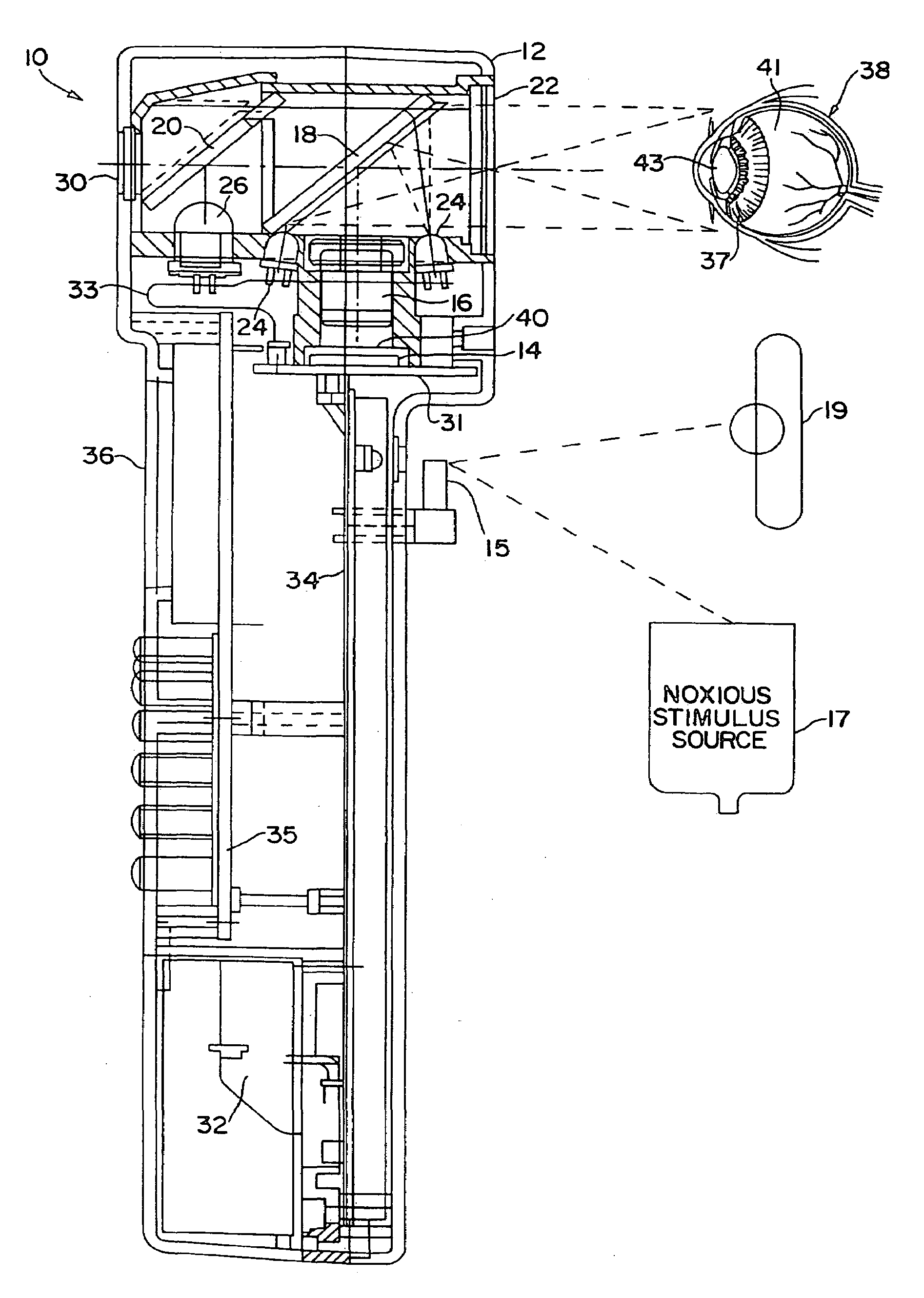
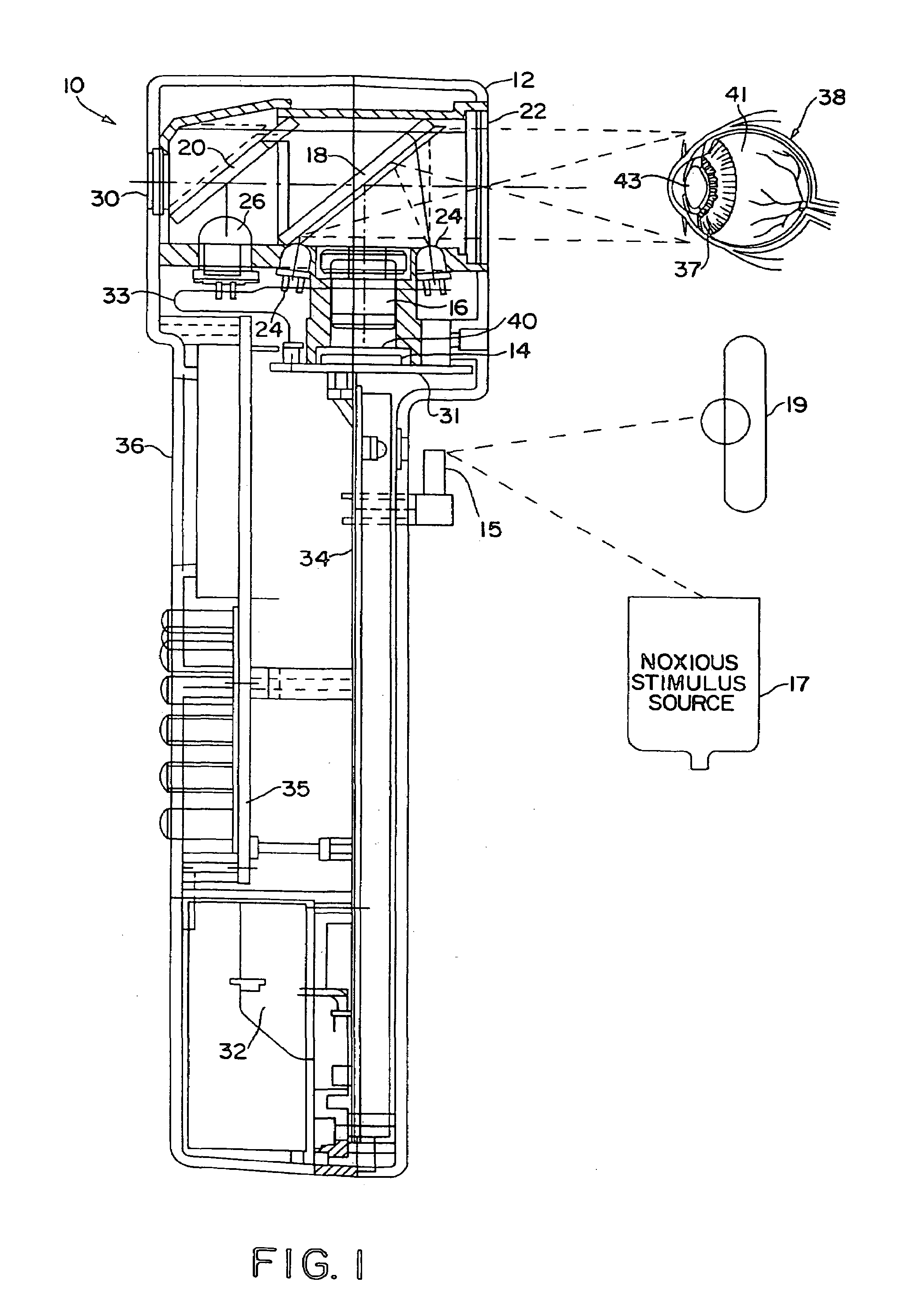
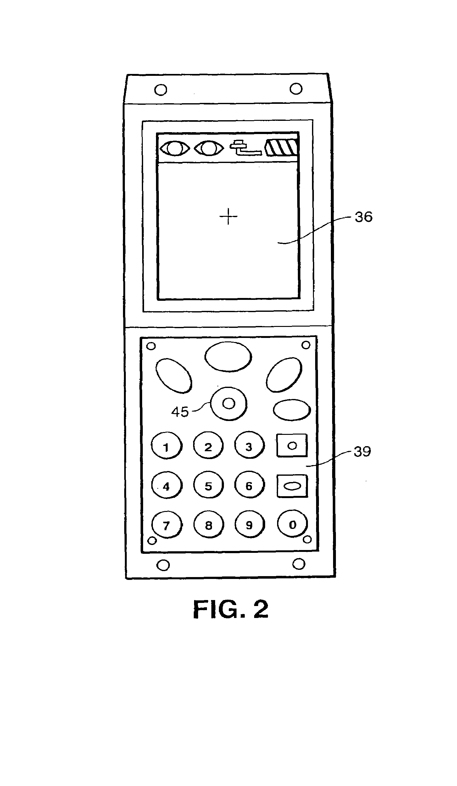
[0045]Turning now to the drawings, FIG. 1 provides a cross-sectional view of a hand-held pupilometer 10 in accordance with the present invention. FIG. 2 provides an illustration of a liquid crystal display and key pad that may be provided on the hand-held pupilometer 10, and FIG. 3 is an enlarged cross-sectional view of an imaging section of the hand-held pupilometer 10.

[0046]As shown in FIGS. 1–3, the pupilometer 10 preferably includes a housing 12 wherein an imaging sensor 14, an objective lens 16, first and second beam splitters 18 and 20, a shield 22, four infrared (IR) LEDs 24, two yellow LEDs 26, a blue LED 28 (shown in FIG. 4), a reticle 30, a battery 32, an image signal processing board 34 and a liquid crystal display 36 are mounted. Stated somewhat differently, the pupilometer may comprise a viewing port (reticle 30 and shield 22), an imaging system (objective lens 16, imaging sensor 14 and rela...


PUM


Abstract

A pupilometer having a pupil irregularity or non-uniformity detection capability. The pupilometer may comprise an imaging sensor for generating signals representative of a pupil of an eye, a data processor; and a program executable by the data processor for enabling the data processor to process signals received from the imaging sensor and to thereby identify one or more regions of non-uniformity within an image of a perimeter of the pupil. The pupilometer may incorporate several innovative calibration and thresholding routines and may provide the basis for an innovative medical diagnostics system, when coupled to a network containing a suitable medical database and data processing hardware.

Description

[0001]This is a continuation of U.S. patent application Ser. No. 09 / 711,675, filed Nov. 9, 2000 now U.S. Pat. No. 6,820,979, which is a continuation-in-part of U.S. patent application Ser. No. 09 / 523,778, filed Mar. 13, 2000, now U.S. Pat. No. 6,260,968, which is a continuation of U.S. patent application Ser. No. 09 / 298,670, filed Apr. 23, 1999, now U.S. Pat. No. 6,116,736. This further claims priority from International Application No. PCT / US / 00 / 10655, filed Apr. 21, 2000. All of the above mentioned applications are incorporated herein by reference.FIELD OF THE INVENTION[0002]The present invention relates generally to pupilometry systems and, more particularly, to pupilometry systems having a pupil irregularity detection, pupil tracking, and pupil response detection capability, as well as glaucoma screening capability, corneal topography measurement capability, intracranial pressure detection capability, and ocular aberration measurement capability. In one particularly innovative a...

Claims


Application Information

Patent Timeline
Patent Type & Authority Patents(United States)
IPC IPC(8): A61B3/10A61B3/11A61B5/16
CPCA61B3/112A61B5/16A61B5/163A61N1/36046A61N2005/0648
Inventor STARK, LAWRENCE W.PRIVITERA, CLAUDIO M.SIMINOU, KAMRANOLIVER, JEFFREY
Owner NEUROPTICS
Why Eureka
Try Eureka