Connector for flexible printed circuit

a flexible printed circuit and connector technology, applied in the direction of coupling contact members, coupling device connections, coupling parts engagement/disengagement, etc., can solve the problems of fpc connectors that are prone to be dragged out of the open mouth, insufficient connection relationship of this kind of fpc connectors, and a lot of wear, so as to achieve reliable connection

Inactive Publication Date: 2006-12-12
HON HAI PRECISION IND CO LTD
View PDF5 Cites 47 Cited by
  • Summary
  • Abstract
  • Description
  • Claims
  • Application Information

AI Technical Summary

Benefits of technology

[0008]An object of the present invention is to provide an FPC connector in which an FPC can be reliably connected.

Problems solved by technology

However, the connection relationship of this kind of FPC connector is not reliable enough because that any unmeant drag or pull incautiously put on the FPC may cause the cam portions to reverse so as to loose the FPC, and therefore the FPC is apt to be dragged out of the open mouth.
However, as the shaft portions of the actuator are of oval-shapes, rather than round shapes, they would have a lot of wear during their pivotal movement between the sharp shear edges of the connection and pressure receiving beams of the terminals, especially since the shaft portions are made from resin material whereas the connection and pressure receiving beams of the terminals are made from metal material.
The high wear of the shaft portions may disable the actuation function of the actuator and thus can't be ignored.
Further, the shaft portion of oval-shape would be angled to wedge up the pressure receiving beam and then escaping out of the space between the connection and pressure receiving beams during initial stroke, or it may become wedged between the connections beam and the projection of the pressure receiving beam, causing binding and / or damage of the actuator.
Furthermore, as the terminal must be shaped to provide a relatively large clearance between the connection and pressure receiving beams for the major axis of the oval shaft portion, it cause strength concerns for the design of the pressure receiving beam in lower profile connectors.

Method used


Image

  • Connector for flexible printed circuit
  • Connector for flexible printed circuit
  • Connector for flexible printed circuit

Examples


Embodiment Construction

[0020]Reference will now be made to the drawing figures to describe the preferred embodiment of the present invention in detail.

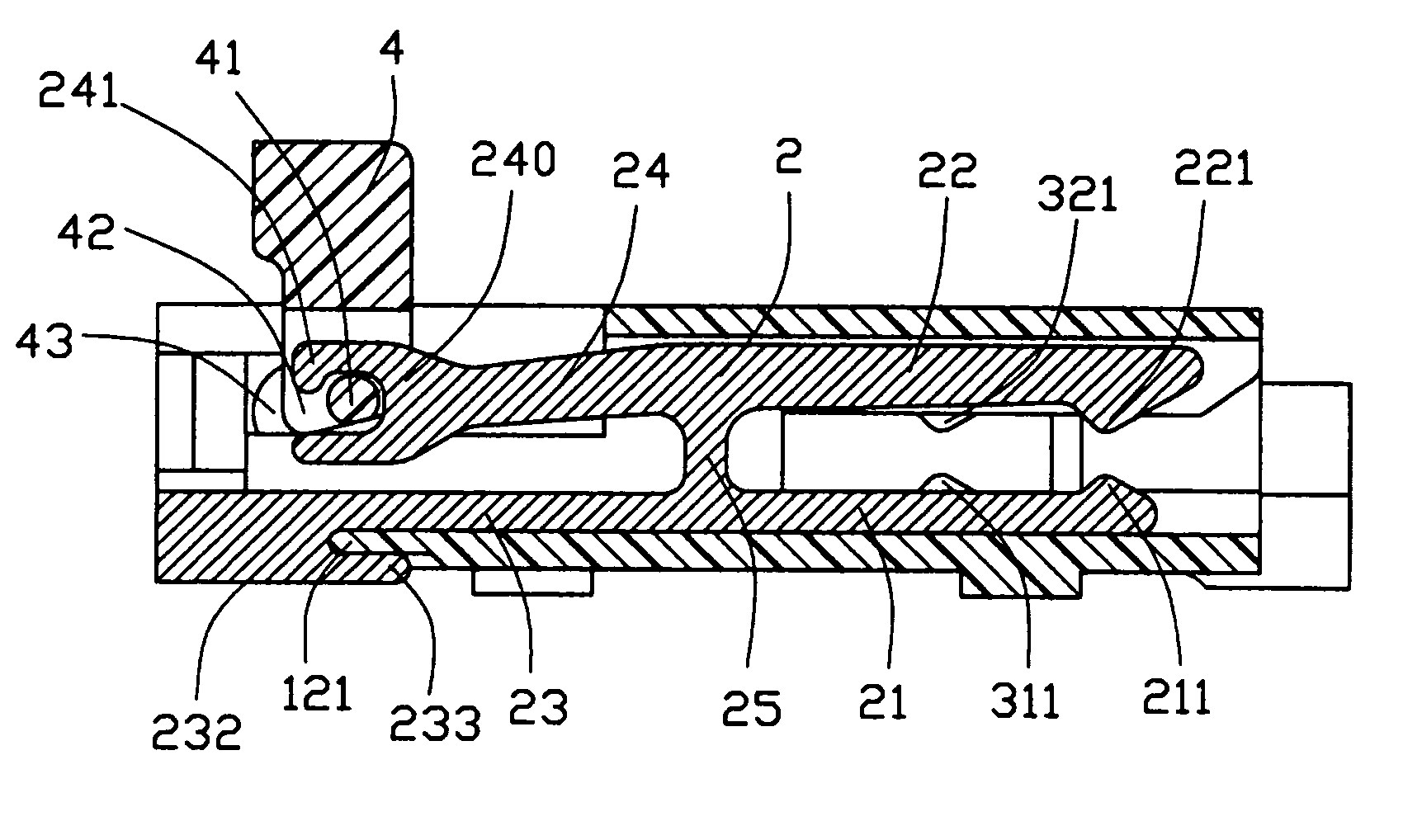
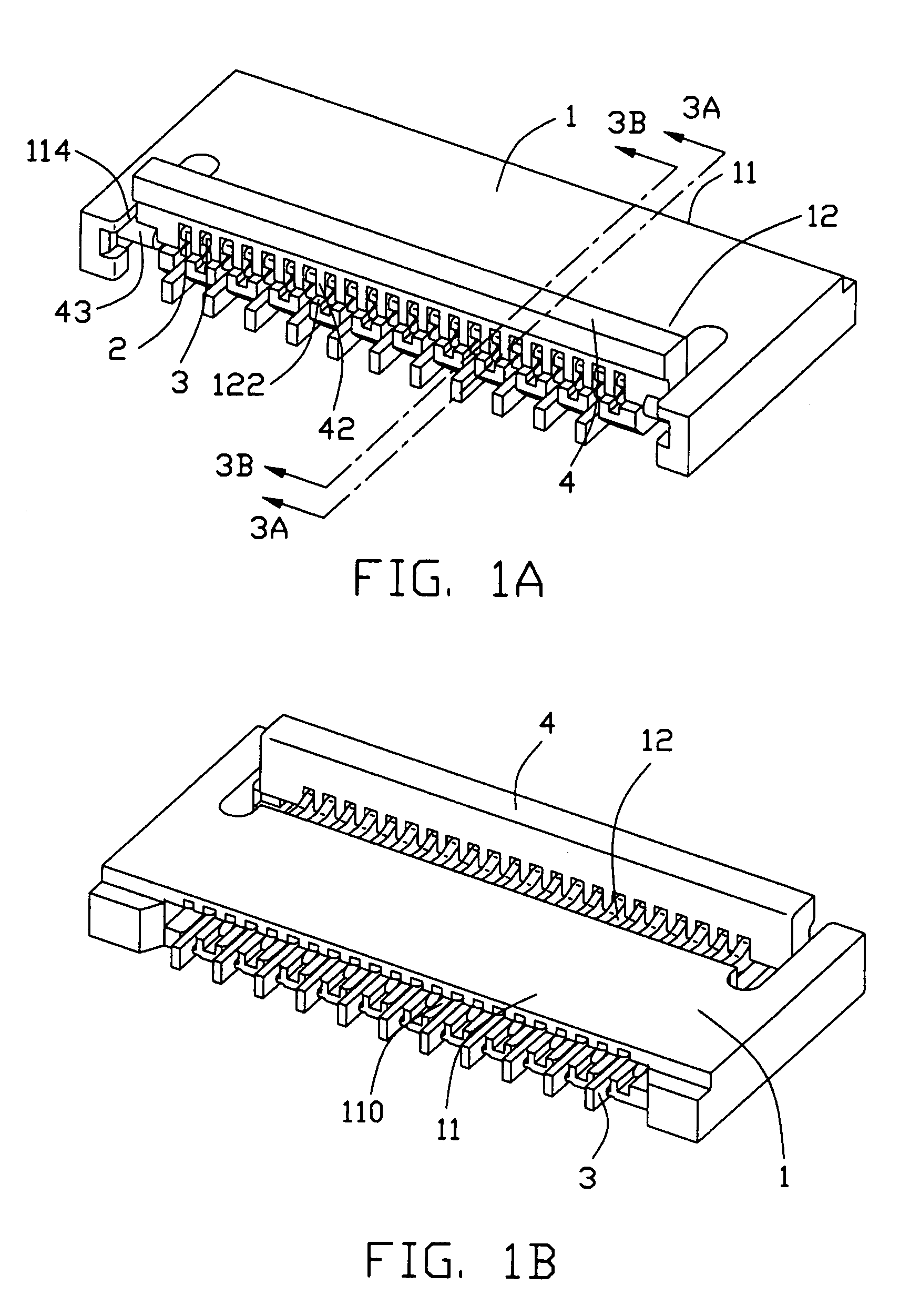
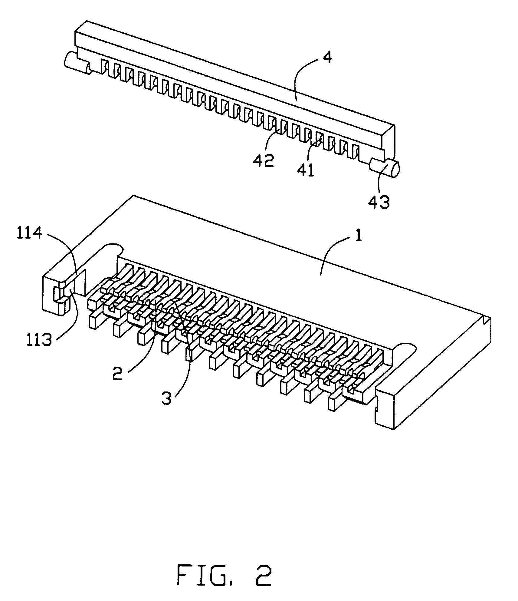
[0021]Referring to FIGS. 1–5, an FPC connector for connecting an FPC 5 (shown in FIGS. 4A and 4B) to a board or the like in accordance with a preferred embodiment of the present invention comprises a plurality of terminals, including two types of terminals, first terminals 2 and second terminals 3, an actuator 4 which is pivotally moved to urge the terminals 2, 3 to connect with the FPC 5, and an insulative housing 1 holding the terminals 2, 3. The housing 1 comprises a front section 11 providing an open mouth 110 for receiving the FPC 5 and a rear section 12 providing a space for operation of the actuator 4.

[0022]First, the terminals 2, 3 will be explained. The first terminals 2 and second terminals 3 are alternately arranged in the housing 1 in a side-by-side fashion. As best shown in FIGS. 3A and 3B, both the first terminal 2 and second terminal 3 are H-...


PUM


Abstract

A connector for a sheet-like member includes a housing (1) providing an open mouth (110) for receiving the sheet-like member and a support surface (122); terminals (2, 3) arranged in the housing and each comprising a fulcrum portion (25, 35), a contact beam (22, 32) extending into the open mouth from the fulcrum portion and a pivot beam (24, 34) extending in opposite direction to the contact beam from the fulcrum portion; and an actuator (4) rotatable between an open and a closed positions. The actuator has shaft portions (41) pivotally engaging with the pivot beams and cam portions (42) between the shaft portions and rotatably supported on the support surface. The shaft portions will urge upwards the pivot beams to force the contact beams against the sheet-like member with aid of the fulcrum portions while the actuator is rotated from the open position to the closed position.

Description

BACKGROUND OF THE INVENTION[0001]1. Field of the Invention[0002]The present invention relates to an electrical connector, and more particularly to an electrical connector for a sheet-like connection member such as a flexible printed circuit or cable (FPC), a flexible flat cable (FFC) and so forth. All of these cables and circuit hereafter will be generally referred to as “FPC” for simplification.[0003]2. Description of Related Art[0004]FPC connectors are roughly classified into two kinds. Typical FPC connectors of the first kind are disclosed in U.S. Pat. Nos. 6,099,346 and 6,755,682, and they generally have a plurality of terminals, and a housing fixing the terminals. Each of the terminals is substantially in the form of a U-shape and mainly composed of a contact beam adapted to contact an FPC, and a pivot beam opposed to and extending substantially parallel to the contact beam. Those U-shaped terminals are side-by-side arranged in the housing and define an open mouth together with...

Claims


Application Information

Patent Timeline
Patent Type & Authority Patents(United States)
IPC IPC(8): H01R13/62H01R12/71H01R12/79
CPCH01R12/774H01R12/79H01R12/88H01R12/57
Inventor GILLESPIE, BRIAN J.WALKER, KEVIN E.MALEHORN, II, RICHARD
Owner HON HAI PRECISION IND CO LTD
Why Eureka
Try Eureka