Engine exhaust gas purification device

a technology for purifying devices and engines, applied in the direction of electrical control, exhaust treatment electric control, separation process, etc., can solve the problem that the amount of correct ash deposits cannot be estimated

Active Publication Date: 2006-12-12
NISSAN MOTOR CO LTD
View PDF11 Cites 20 Cited by
  • Summary
  • Abstract
  • Description
  • Claims
  • Application Information

AI Technical Summary

Benefits of technology

[0005]It is therefore an object of this invention to correctly determine an ash amount ASH a...

Problems solved by technology

However, in the prior art, the ash deposit amount was estimated from the engine running time or vehicle running distance, so there is ...

Method used


Image

  • Engine exhaust gas purification device
  • Engine exhaust gas purification device
  • Engine exhaust gas purification device

Examples


Embodiment Construction

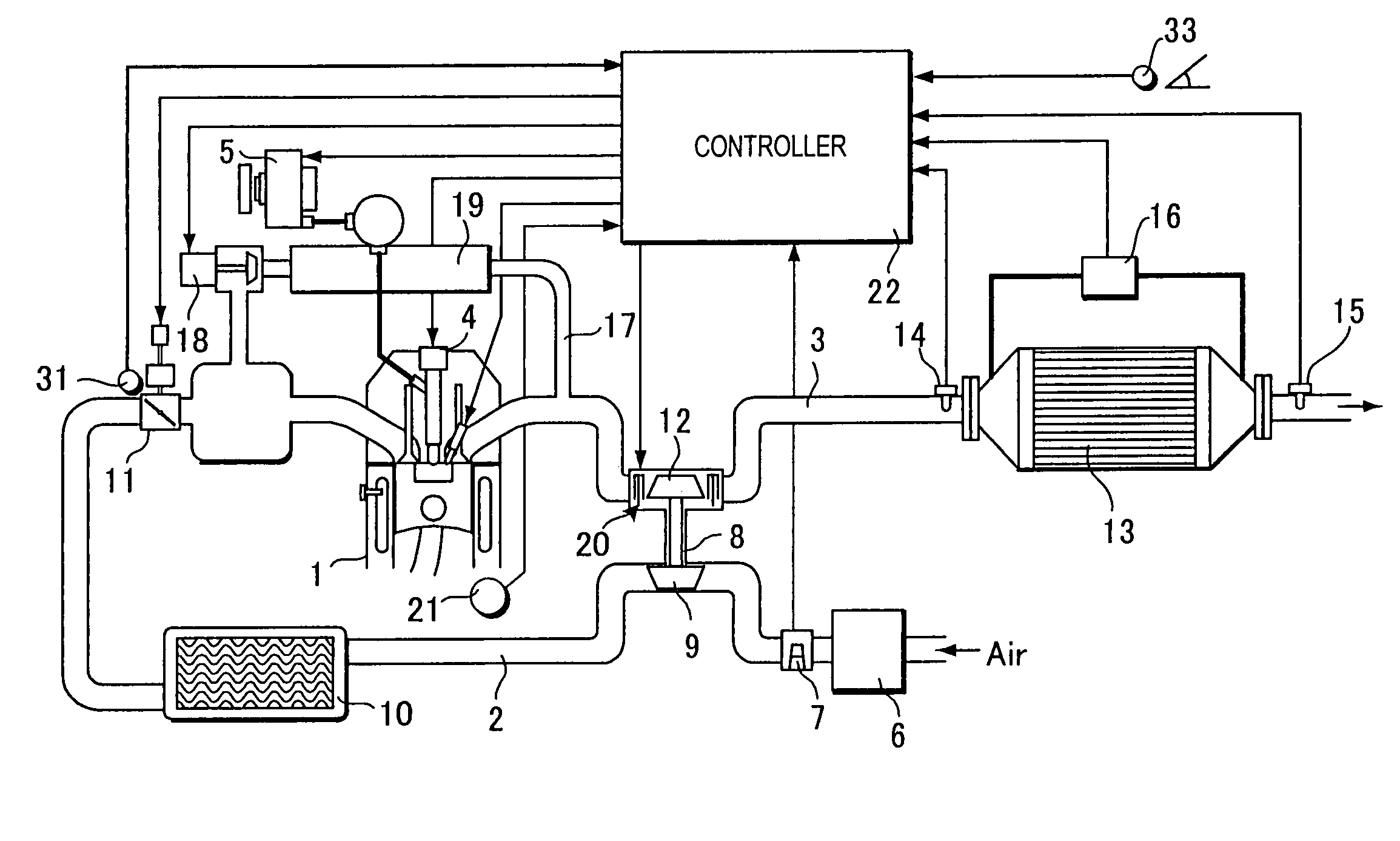
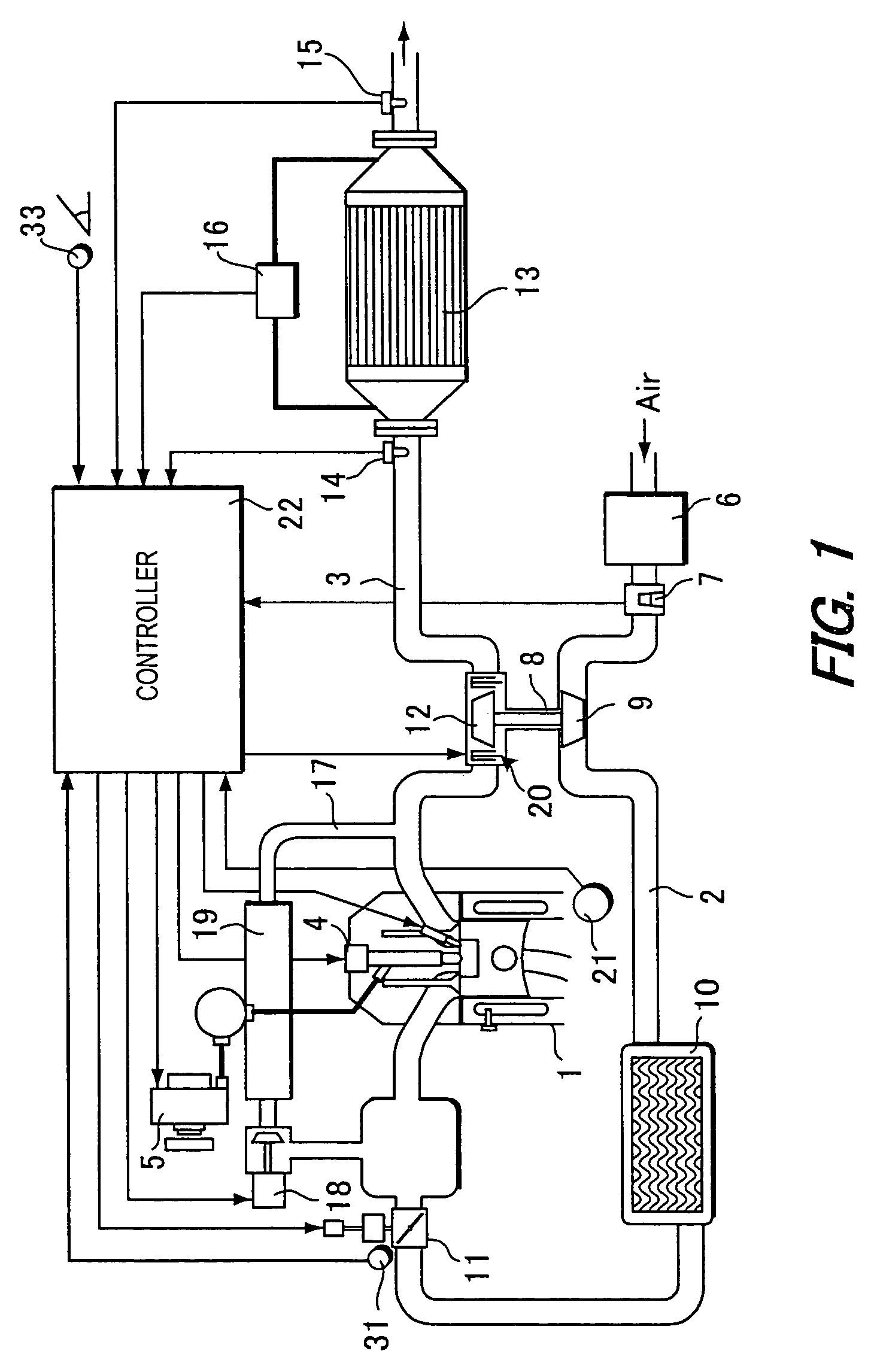
[0016]Referring to FIG. 1, an engine system to which this invention can be applied is equipped with an engine 1, an air passage 2 for introducing air and an exhaust passage 3 for discharging the exhaust gas produced from the engine 1. The engine system is preferably used for a vehicle. The engine 1 may be a diesel engine, although not limited to a diesel engine. A fuel injector 4 connected to a fuel injection pump 5 is mounted in the engine 1. The air passage 2 is provided with an air cleaner 6, air flow meter 7, compressor 9 of an exhaust gas turbocharger 8, intercooler 10 and throttle valve 11 in sequence from the upstream side. The exhaust passage 3 is provided with a turbine 12 of the exhaust gas turbocharger 8 and a filter 13 which traps particulate matter in the exhaust gas produced from the engine 1 in sequence from the upstream side. If the engine 1 is a diesel engine, the filter 13 may be the so-called diesel particulate filter (DPF).

[0017]The exhaust gas purification devic...


PUM

PropertyMeasurementUnit
Timeaaaaaaaaaa
Flow rateaaaaaaaaaa
Densityaaaaaaaaaa

Abstract

An engine exhaust gas purification device is disclosed. The purification device has a filter (13) which traps particulate matter contained in the exhaust gas from an engine; a differential pressure detection sensor (16) which detects a differential pressure of the filter; a sensor (14, 15, 21, 31, 33) which detects an engine running state, and a microcomputer (22). The microcomputer (22) is programmed to compute an estimated ash amount ASH_a of the filter based on the detected differential pressure; compute an oil consumption amount OC_total based on the detected engine running state; compute an ash density DENS_ASH from the oil consumption amount OC_total and estimated ash amount ASH_a, and compute an ash amount ASH of the filter based on the oil consumption amount OC_total and ash density DENS_ASH.

Description

FIELD OF THE INVENTION[0001]This invention relates to an engine exhaust gas purification device, and more particularly to a technique for correctly determining the replacement timing of a filter which traps particulate matter in engine exhaust gas.BACKGROUND OF THE INVENTION[0002]Tokkai No. 2000-234509 published by the Japanese Patent Office in 2000 discloses an exhaust gas purification device which carries out the purification of particulate matter discharged from a diesel engine or the like. The purification device comprises a filter in the engine exhaust system, the filter being regenerated by oxidizing or incinerating the trapped particulate matter at a predetermined interval.[0003]In addition to combustible particulate matter, non-combustibles (hereafter, referred to as “ash”) mainly from engine oil additives also adhere to the filter. As the ash cannot be burnt in the process of regeneration, after a certain time interval has elapsed, it will cause a pressure loss in the filte...

Claims


Application Information

Patent Timeline
IPC IPC(8): B01D46/00F02D45/00B01D46/42F01N3/02F01N3/023F01N9/00F02B37/00F02M25/07
CPCF01N3/023F01N9/002F01N9/005F01N2430/08F01N2550/04F02B29/0406F02B37/00F02M25/0707F02M25/0718F02M25/0726F02M25/0754F02M25/0755Y02T10/47Y10S55/30Y10S55/10F02M26/05F02M26/15F02M26/22F02M26/46F02M26/47Y02T10/40
Inventor INOUE, TAKAOKAWASHIMA, JUNICHITSUTSUMOTO, NAOYAOTAKE, MAKOTOKONDOU, TERUNORIKOGA, TOSHIMASA
Owner NISSAN MOTOR CO LTD
Why Eureka
Try Eureka