Virtual sensor mast

Active Publication Date: 2006-12-12
LOCKHEED MARTIN CORP
View PDF10 Cites 83 Cited by
  • Summary
  • Abstract
  • Description
  • Claims
  • Application Information

AI Technical Summary

Problems solved by technology

One significant challenge presented by unmanned, robotic vehicles is situational awareness.
A common limitation for any of these technologies is the vantage point of the instrument.
For instance, the height of the vantage point inherently limits the field of view for any sensor, which is particularly problematical for long-range sensors.
Sensors for which this limitation is particularly problematical are sometimes mounted to a mast extending upwardly from the vehicle.
However, simply positioning the sensors high on the vehicle's body or on a sensor mast may offer only

Method used


Image

  • Virtual sensor mast
  • Virtual sensor mast
  • Virtual sensor mast

Examples


Embodiment Construction

[0034]Illustrative embodiments of the invention are described below. In the interest of clarity, not all features of an actual implementation are described in this specification. It will of course be appreciated that in the development of any such actual embodiment, numerous implementation-specific decisions must be made to achieve the developers'specific goals, such as compliance with system-related and business-related constraints, which will vary from one implementation to another. Moreover, it will be appreciated that such a development effort, even if complex and time-consuming, would be a routine undertaking for those of ordinary skill in the art having the benefit of this disclosure.

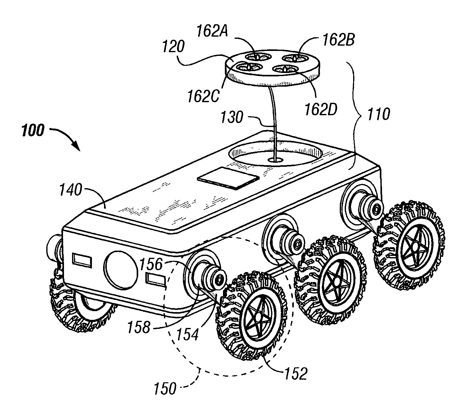
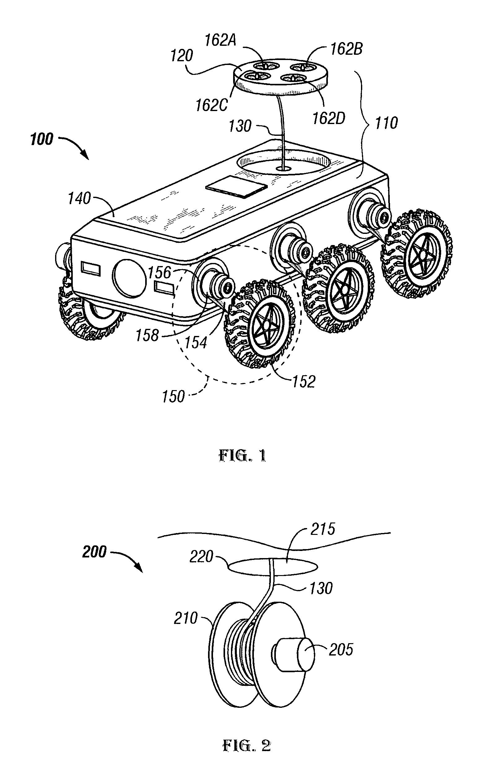
[0035]FIG. 1 illustrates an unmanned ground vehicle (“UGV”) 100 employing a virtual sensor mast 110 in accordance with the present invention. The virtual sensor mast 110 comprises an unmanned airborne vehicle (“UAV”) 120 communicating with the ground vehicle over a tether 130. The UAV 120 includes...


PUM


Abstract

A virtual sensor mast for a ground vehicle and a method for operating a ground vehicle using a virtual sensor mast are disclosed. The virtual sensor mast includes an unmanned airborne vehicle capable of lifting itself from the ground vehicle upon deployment therefrom; a sensor suite mounted to the unmanned airborne vehicle; and a tether between the unmanned airborne vehicle and the ground vehicle over which the sensor suite is capable of communicating sensed data upon deployment. The method includes elevating a tethered unmanned airborne vehicle from the ground vehicle to a predetermined height; sensing environmental conditions surrounding the ground vehicle; and terminating the deployment.

Description

[0001]We claim the earlier effective filing date of co-pending U.S. Provisional Application Ser. No. 60 / 449,271, entitled “Unmanned Ground Vehicle,” filed Feb. 21, 2003, in the name of Michael S. Beck, et al., for all common subject matter.BACKGROUND OF THE INVENTION[0002]1. Field of the Invention[0003]This invention pertains to remote sensing for ground vehicles and, more particularly, to a technique for achieving a higher vantage point from which the sensing occurs.[0004]2. Description of the Related Art[0005]One significant challenge presented by unmanned, robotic vehicles is situational awareness. Situational awareness includes detection and identification of conditions in the surrounding environment. Robotic vehicles typically carry a variety of instruments to remotely sense the surrounding environment. Commonly used instruments include technologies such as:[0006]acoustic;[0007]infrared, such as short wave infrared (“SWIR”), long wavelength infrared (“LWIR”), and forward lookin...

Claims


Application Information

Patent Timeline
IPC IPC(8): G01M17/00B60K7/00B60K17/04B60K17/356B60T1/06B62D61/10B62D61/12B64B1/50B64C27/20B64C39/02
CPCB60K17/356B60T1/062B62D61/10B62D61/12B64B1/50B64C27/20B64C39/022B64C39/024B64C39/028B60K17/046B60K7/0007B64C2201/208B64C2201/027B64C2201/042B64C2201/044B64C2201/108B64C2201/127B64C2201/148B64C2201/162B64U50/11B64U10/13B64U50/19B64U30/20B64U2101/30B64U2201/202B64U50/14B64U80/86
Inventor BECK, MICHAEL S.CHUN, WENDELL H.STINCHCOMB, JON T.
Owner LOCKHEED MARTIN CORP
Why Eureka
Try Eureka