Configurable clamp assembly

Inactive Publication Date: 2006-12-19
KONOLD DONALD ROSS
View PDF12 Cites 28 Cited by
  • Summary
  • Abstract
  • Description
  • Claims
  • Application Information

AI Technical Summary

Problems solved by technology

These designs address, in each case, a singular application and are not adaptable for uses other than the intended design.

Method used


Image

  • Configurable clamp assembly
  • Configurable clamp assembly
  • Configurable clamp assembly

Examples


first embodiment

[0036]The first embodiment is a standard installation that requires minimum insulation and isolation provisions, but requires that a Configurable Clamp Assembly (10) be adhesively secured to a mounting surface (45) because surface penetrating fasteners cannot be used.

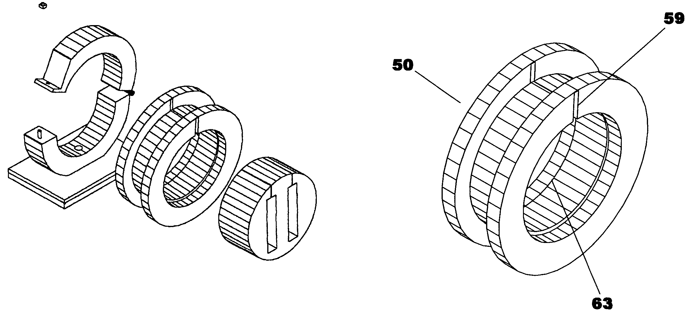
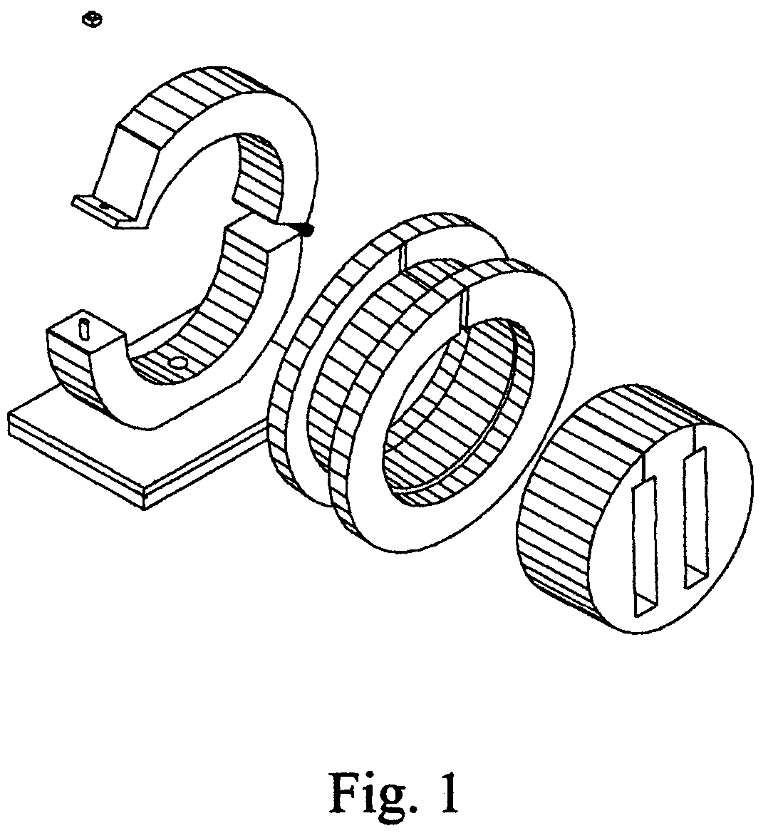
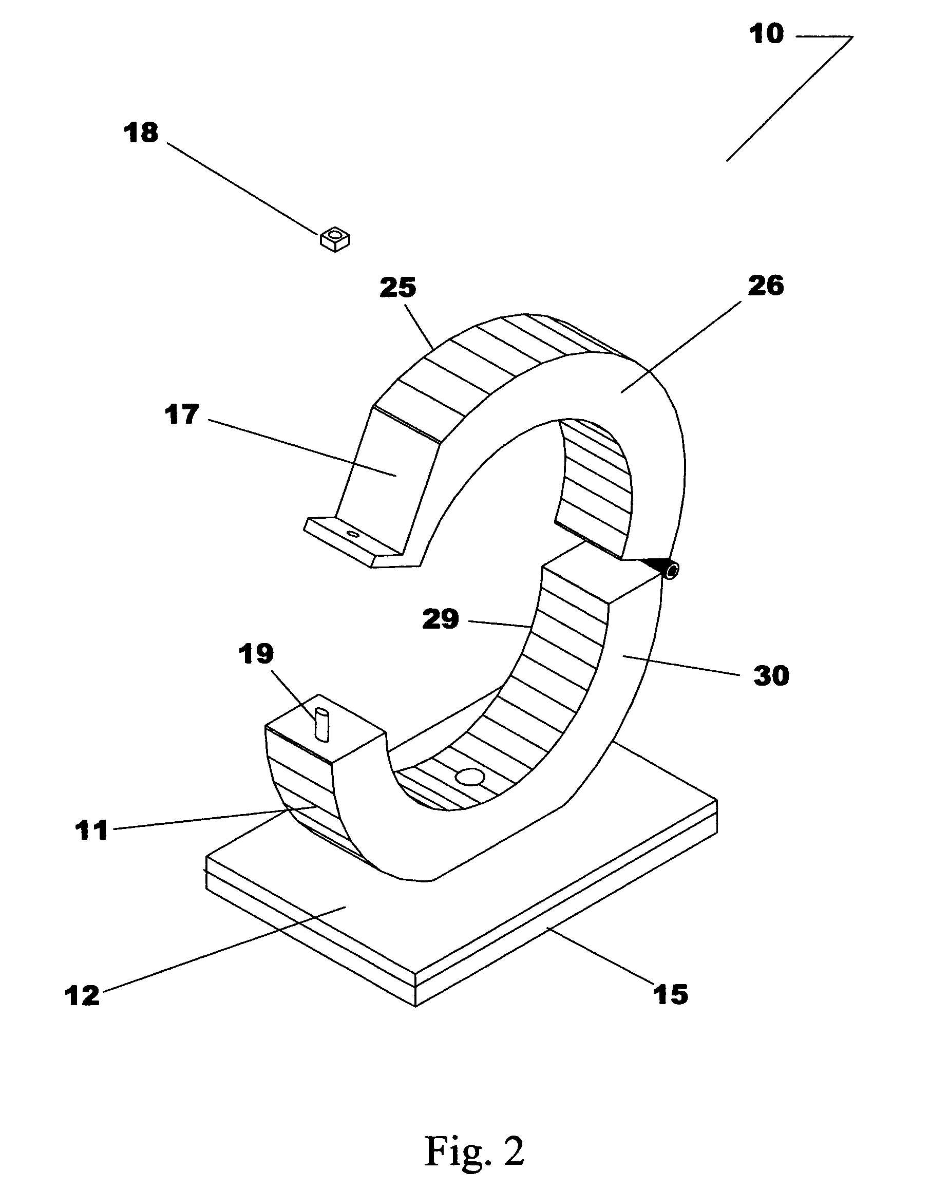
[0037]The first embodiment of the Configurable Clamp Assembly (10) as shown in the isometric view of FIG. 2 and the cross section view of FIG. 3 includes a Saddle (11) with an integrated Rectangular Flat Base Plate (12) including a Base Plate Top Surface (13) and a Base Plate Bottom Surface (14) and a Yoke (17) that is connected to the Saddle (11) by a Hinge (16).

[0038]The Saddle (11) is an arcuate structure defined by a Saddle Inner curve (28), a Saddle Outer Curve (27) and a Saddle 1st Side (29) and a Saddle 2nd Side (30). The Saddle (11) width is fixed by the distance between the Saddle 1st Side (29) and the Saddle 2nd Side (30). The Saddle (11) is terminated by a Saddle 1st End Surface (34) and a 2nd Saddle End Surf...

second embodiment

[0045]In the second embodiment, rapid installation that is more permanent is desired and surface penetrating fasteners are allowed but only a standard installation requiring minimum insulation and isolation provisions are needed.

[0046]In this second embodiment of the Configurable Clamp Assembly (10) as shown in the section views of FIGS. 5 and 6 includes a Saddle (11) with an integrated Rectangular Flat Base Plate (12) including a Base Plate Top Surface (13) and a Base Plate Bottom Surface (14) and a Yoke (17) that is connected to the Saddle (11) by a Hinge (16).

[0047]The Saddle (11) is an arcuate structure defined by a Saddle Inner curve (28), a Saddle Outer Curve (27) and a Saddle 1st Side (29) and a Saddle 2nd Side (30). The Saddle (11) width is fixed by the distance between the Saddle 1st Side (29) and the Saddle 2nd Side (30). The Saddle (11) is terminated by a Saddle 1st End Surface (34) and a 2nd Saddle End Surface (35). The Saddle Inner Curve (28) forms a 1st Semicircular Re...


PUM


Abstract

A configurable clamp assembly for retaining pipe, conduit, cable bundles, waveguides and fiber optic cable that is designed for rapid installation without the need of pre-drilled holes or other mounting surface preparation. The clamp is formed by a saddle structure with integral rectangular flat base plate that receives interchangeable mounting pads and either a securing fastener or adhesive layer that secures the clamp to a mounting surface. A clamping yoke is hingedly secured to the saddle structure that is adapted to fold about the hinge to enclose and retain pipes, conduits or a Collar that engages an interchangeable Insert. The clamping yoke is fastened with a locknut that engages a threaded retaining post, locking the yoke to the saddle. The Insert is provided with various cross section geometries to secure waveguides, fiber optic cables and specially shaped tubing and is designed for insertion into the Collar for special applications.

Description

CROSS-REFERENCE TO RELATED APPLICATIONS[0001]Not ApplicableSTATEMENT REGARDING FEDERALLY SPONSORED RESEARCH OR DEVELOPMENT[0002]Not applicableREFERENCE TO A “SEQUENCE LISTING,” A TABLE, OR A COMPUTER PROGRAM LISTING APPENDIX SUBMITTED ON A COMPACT DISC[0003]Not ApplicableBACKGROUND OF THE INVENTION[0004]1. Field of the Invention[0005]This invention relates to conduits such as pipe, cable, waveguide and supports provided by a universal clamping system formed from a combination clamp and support structure with an interchangeable support structure mounting pad, mounting collar and interchangeable insert with a variety of cross section geometries to accommodate pipe, cable, waveguide and conduit shapes as required. The term conduit as used through the remainder of this description shall be taken as a generic term for pipes, cables, tubes, rods, wires, waveguides and other conveyances for liquids, electrical current and etc.[0006]2. Description of the Prior Art[0007]The prior art contain...

Claims


Application Information

Patent Timeline
Patent Type & Authority Patents(United States)
IPC IPC(8): F16L3/12
CPCF16L3/1075F16L3/127H02G3/266F16B2/10
Inventor KONOLD, DONALD ROSS
Owner KONOLD DONALD ROSS
Why Eureka
Try Eureka