Hydraulic hammer having a sealing bushing

a technology of hydraulic hammer and sealing bushing, which is applied in the direction of portable percussive tools, drilling machines and methods, marine site engineering, etc., can solve the problems of material breaking, laborious installation of seals at the lower end of percussion pistons, and laborious sealing changes in connection with maintenance, so as to achieve less precision, less maintenance, and more freedom of choi

Active Publication Date: 2006-12-26
SANDVIK TAMROCK
View PDF15 Cites 28 Cited by
  • Summary
  • Abstract
  • Description
  • Claims
  • Application Information

AI Technical Summary

Benefits of technology

[0007]An advantage of the invention is that the sealing bushing can be detached through the lower part of the frame without having to dismantle the hydraulic part of the percussion device. Consequently, there is no need to detach the percussion piston, bearings, valves, or other hydraulic components when the sealing bushing is changed, which enables rapid and less complex maintenance. Since the sealing bushing can be changed without dismantling the hydraulic part, entering of impurities into the hydraulic part can be avoided. Moreover, since the sealing bushing does not function as a bearing for the percussion piston, it can be manufactured with less precision and, in addition, there is more freedom of choice as regards the dimensioning and structure of the sealing bushing and the characteristics of the material it is made of.
[0008]An essential idea of an embodiment of the invention is that the sealing bushing is an integral part of the tool bushing. In that case the hydraulic hammer may consist of fewer parts and, in addition, the assembly and maintenance of the hammer may be rapid. Further, it may have a simple structure, because the tool bushing and the sealing bushing part at the upper end thereof may be attached in place by means of a tool-retaining pin.
[0009]An essential idea of another embodiment of the invention is that at least a portion of the lower part of the percussion piston is bearing-mounted to bearing surfaces formed to the frame of the hydraulic hammer. With a bearing surface formed directly to the frame, the manufacture and mounting of a separate bearing bushing is avoided. In addition, it is relatively simple to machine a bearing surface that is accurate in dimension and shape directly to the frame. Bearings formed to the frame are also rigid and provide good support for the percussion piston. It is also possible to form all percussion piston bearings directly to the frame. In some cases, however, the upper end of the percussion piston may be bearing-mounted by means of a separate bearing bushing or the like.
[0010]An essential idea of yet another embodiment of the invention is that the inner circumference of the sealing bushing is provided with at least two seals arranged at a predetermined distance from one another in axial direction. In the stroke direction, the first seal is the actual lower seal arranged to prevent hydraulic fluid from flowing away from the percussion device and out of the hydraulic part of the percussion device. This keeps the hydraulic hammer clean, and hydraulic fluid does not get into the environment. Still viewed in the stroke direction, the second seal is what is known as a dust seal, which is arranged to prevent outside impurities from entering into the percussion device through the lower end of the hydraulic hammer. This prevents impurities from penetrating into the hydraulic fluid of the hydraulic hammer and thereby to the hydraulic system of the entire basic machine. Preventing impurities from entering into the hammer also enables premature wear of the hammer and disturbances caused by impurities to be avoided.
[0011]An essential idea of an embodiment of the invention is that the percussion device comprises at least one groove arranged before the first, i.e. lower, seal of the sealing bushing, in the stroke direction. In addition, the groove is connected to a pressure fluid discharge channel, whereby pressure fluid leaked through the clearances between the percussion piston and the frame is allowed to flow into the groove and further to the discharge channel.
[0012]An essential idea of yet another embodiment of the invention is that the sealing bushing is a separate piece supported in axial direction in place by means of a tool bushing. In that case the sealing bushing does not necessarily have to be provided with any separate means of attachment, which may simplify the structure of the hammer.

Problems solved by technology

At the same time when delivering strokes with the percussion piston, the tool is pressed against the material to be broken, whereby the tool penetrates into the material by the impact of the strokes and the pressing, and causes the material to break.
However, a problem with hydraulic hammers is the arrangement of seals at the lower end of the percussion piston, i.e. at its tool side end.
In current solutions the mounting of the seals and the changing thereof in connection with maintenance is laborious.

Method used


Image

  • Hydraulic hammer having a sealing bushing
  • Hydraulic hammer having a sealing bushing
  • Hydraulic hammer having a sealing bushing

Examples


Embodiment Construction

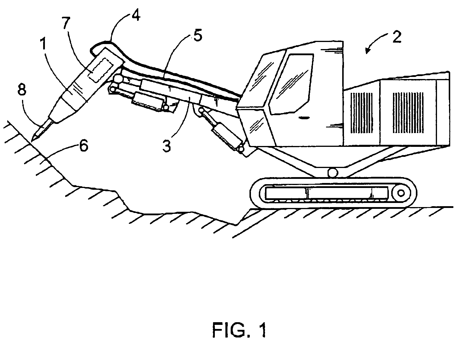
[0023]In FIG. 1 a hydraulic hammer 1 is arranged to a free end of a beam 3 of an excavating machine 2. The hydraulic hammer 1 has a supply channel 4 for supplying hydraulic fluid to the hammer and, further, a discharge channel 5 for leading away the fluid. Thus the hydraulic hammer 1 may be connected to a hydraulic system of the excavating machine 2. With the beam 3 the hydraulic hammer 1 is pressed against material 6 to be broken, while at the same delivering strokes with a percussion device 7 of the hammer to a tool 8 attached to the hammer, the tool transmitting the strokes to the material. The hydraulic hammer 1 may be arranged to any movable basic machine or to a beam mounted to a fixed base, for example.

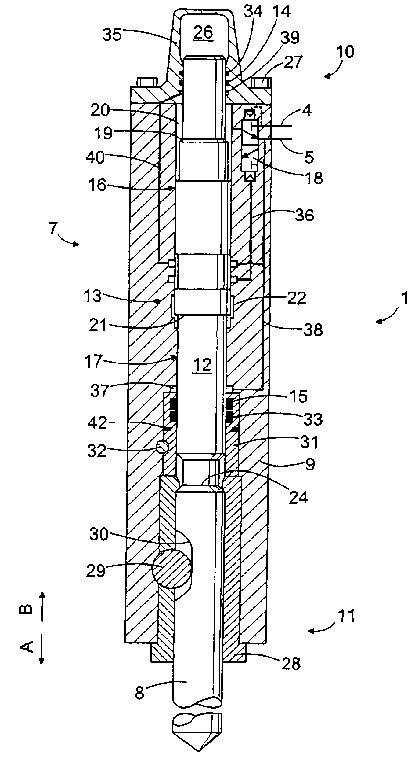
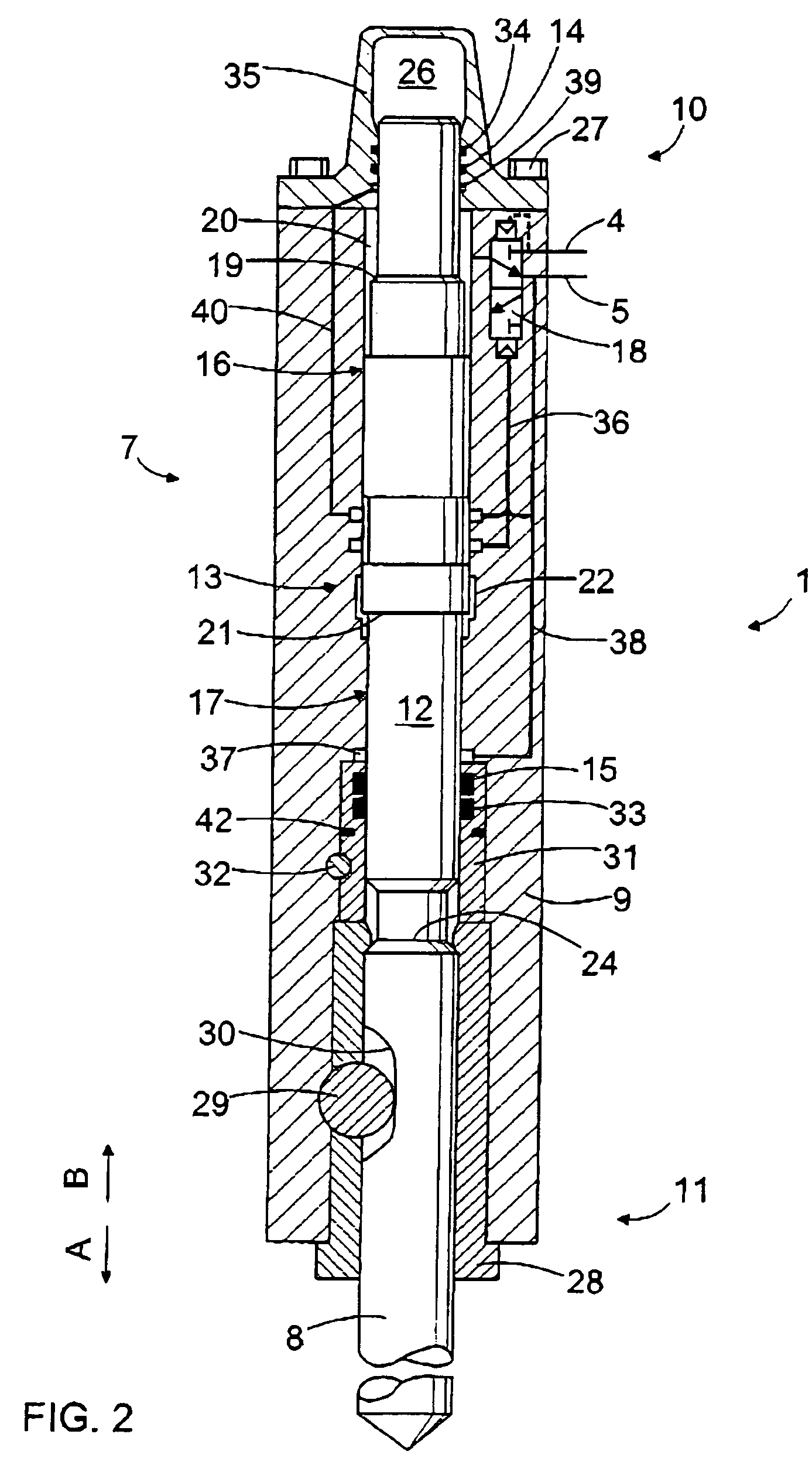
[0024]The hydraulic hammer 1 of FIG. 2 comprises an elongated frame 9 having an upper end 10 and a lower end 11. The tool 8 is arranged to the lower end 11 of the frame 9. In the embodiment of FIG. 2 the frame 9 consists of a single frame piece and thus it may be very rigid and...


PUM

PropertyMeasurementUnit
hydraulic pressureaaaaaaaaaa
pressureaaaaaaaaaa
inner diameteraaaaaaaaaa

Abstract

A hydraulic hammer having a sealing bushing includes a percussion piston that delivers strokes to a tool. A lower part of the percussion piston is sealed with respect to a frame by the sealing bushing, which includes one or more lower seals. The sealing bushing does not contribute to the bearing of the percussion piston and it is arranged in place through the lower end of the hydraulic hammer.

Description

BACKGROUND OF THE INVENTION[0001]The invention relates to a hydraulic hammer comprising: a frame, which is an elongated piece and comprises an upper end and a lower end; a percussion device having an elongated percussion piston that is reciprocatingly movable into a stroke direction and a return direction by means of hydraulic pressure. The invention further relates to a tool bushing for supporting a tool to a hydraulic hammer.[0002]A hydraulic hammer is used as an additional device in an excavating machine or other basic machine for example for purposes of breaking rock, concrete, or some other relatively hard material. The hydraulic power needed by the hydraulic hammer can be led to the hammer's percussion device from a hydraulic circuit of the basic machine. The percussion device delivers strokes to a tool attached to the hydraulic hammer and the tool transmits the strokes to the material to be broken. The percussion device usually includes a percussion piston, which makes a reci...

Claims


Application Information

Patent Timeline
Patent Type & Authority Patents(United States)
IPC IPC(8): B23B45/16B25D9/00B25D9/02B25D9/04B25D9/06B25D9/14B25D9/18E02B3/16
CPCB25D9/145B25D9/18B25D2222/57B25D2250/331B25D2250/345B25D2250/365E02F3/966B65H35/0086B65H35/0026B65H2301/515326B65H2301/5154B65H2301/5151B65H2701/377
Inventor HURSKAINEN, ARVOJUVONEN, ESKO
Owner SANDVIK TAMROCK
Why Eureka
Try Eureka