Method and device for determining the instantaneous mass flow of pulsating flows

a technology of instantaneous mass flow and pulsating flow, which is applied in the direction of liquid/fluent solid measurement, machines/engines, instruments, etc., can solve the problems of inability to continuously measure a periodically pulsating flow, high cost of providing a device for the performance of lda, and inability to continuously measure a periodic pulsating flow. , to achieve the effect of simple device setup, quick and accurate measurement, and less effor

Inactive Publication Date: 2011-02-01
FRIEDRICH ALEXANDER UNIV ERLANGEN NUERNBERG
View PDF4 Cites 0 Cited by
  • Summary
  • Abstract
  • Description
  • Claims
  • Application Information

AI Technical Summary

Benefits of technology

[0008]The suggested method makes possible quick and exact determination of the instantaneous rate of the mass flow of a fluid or a liquid. The suggested method permits determination of the instantaneous rate of the mass flow with an extremely high time resolution. In particular, the mass flow of the fuel for injection units of motor vehicles can be measured exactly for each injection procedure. This makes precise control of the injection procedure possible. This can improve the efficiency of an engine and prevent undesired incomplete combustion of fuel. In particular, the suggested method also makes possible an exact control of multiple injection procedures during one stroke. The aforementioned advantages are particularly made possible by the suggested measurement of the pressure gradient and the calculating steps which are quickly accomplishable with today's process computers using the table. The suggested measurement of the pressure gradient makes possible—in contrast to the known optical methods in accordance with the state of technology—a continuous determination of the instantaneous rate of the mass flow of the fluid during one and the same period.
[0021]The suggested device is robust and makes possible a quick and exact measurement of the instantaneous rate of the mass flow. It is not prone to malfunctions and can be manufactured with less effort—in comparison to the state of technology.
[0022]In accordance with an advantageous embodiment, a triggering unit is provided for starting a calculation sequence comprising the steps bb1) to bb3). Furthermore, it is useful that a flow control element is provided, preferably a valve, which can be controlled with the triggering unit. This makes a particularly simple setup of the device possible. This simultaneously ensures that, for example, a frequency of the operating times of the calculation sequences is correlated with the opening or closing times of the valve.
[0023]In accordance with a further embodiment of the invention, the means of pressure determination comprises an amplifier with an analog / digital converter connected downstream. This makes digital further processing of the measured signals possible.

Problems solved by technology

A measuring method based on these findings is, for example, also described in U.S. Pat. No. 6,510,842 B2.—However, the methods which are based on the principle of LDA are also disadvantageous in several respects.
A continuous measurement of a periodically pulsating flow is not possible with this.
The provision of a device for the performance of the LDA is expensive.
Apart from this, such a device is sensitive, in particular sensitive to oscillations, and is not suitable for the control or regulation of injection devices for motor vehicles.

Method used


Image

  • Method and device for determining the instantaneous mass flow of pulsating flows
  • Method and device for determining the instantaneous mass flow of pulsating flows
  • Method and device for determining the instantaneous mass flow of pulsating flows

Examples


Embodiment Construction

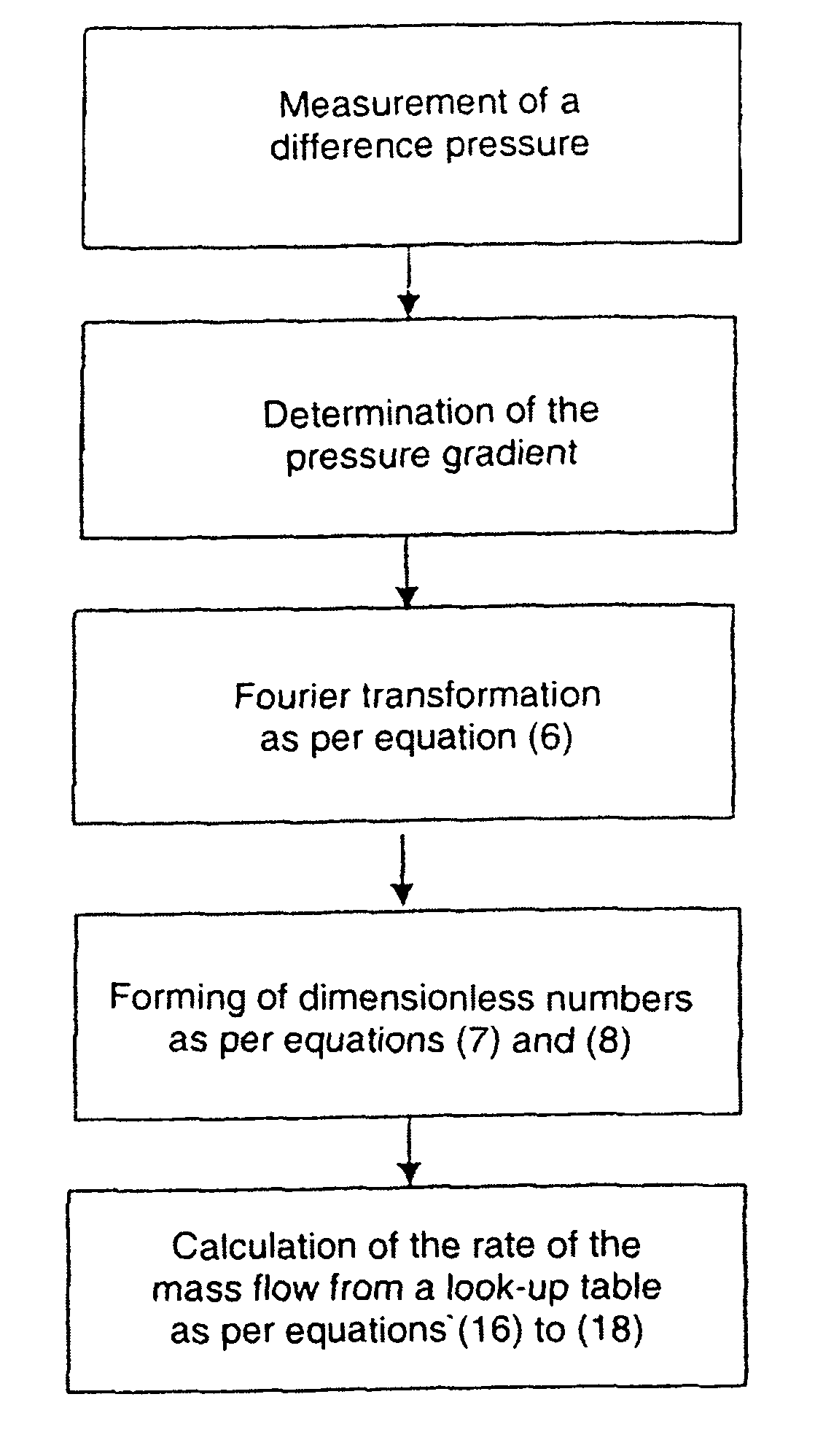
[0039]The theoretical fundamentals of the claimed method will now be discussed in more detail.

[0040]The equation derived from Lambossy (Lambossy, P. (1952), Oscillations forcées d'un liquide incompressible et visqueux dans un tube rigide et horizontal. Calcul de la force frottement, Helv. Physica Acta 25, 371-386) for the velocity field of a harmonically oscillating, fully developed laminar pipe flow can be expanded for any variable-time pressure gradient which can be expressed with the following Fourier series

[0041]∂P∂z=-ρ[p0+∑n=1∞⁢(pn⁢ⅇⅈ⁢⁢n⁢⁢ω⁢⁢t+C.C.)](1)

wherein C.C. stands for the complex conjugating argument. The laminar pipe flow can be described with the aid of a simplified form of the Navier-Stokes equations:

[0042]ρ⁢∂U∂t=-∂P∂z+μ⁡(1r⁢∂∂r⁢(r⁢⁢∂U∂r))(2)

[0043]By using the pressure gradient (∂P / ∂z) from equation (1) in equation (2) one obtains a partial differential equation which describes the velocity field. The linearity of this equation permits the resulting velocity field to...


PUM


Abstract

The invention relates to a method for determining the instantaneous rate of the mass flow of a flow of a fluid pulsating periodically at a frequency f, said method comprising the following steps: a) a pressure gradient in the flow over a certain period (P) is determined, b) the harmonic amplitude of the pressure gradient is calculated by means of Fourier transformation, c) the frequency f and the time t are converted into dimensionless numbers F, t and d) the rate of the mass flow is determined using a table from which at least one corresponding value describing the mass flow rate and / or a phase difference can be deduced for each dimensionless number F of the frequency f.

Description

BACKGROUND OF THE INVENTION AND RELATED ART STATEMENT[0001]The invention relates to a method and a device for the determination of the instantaneous mass flow with pulsating flows.[0002]An analytical solution for any pulsating flows is known from Uchida, S. 1956, “The Pulsating Viscous Flow Superposed on the Steady Laminar Motion of Incompressible Fluid in a Circular Pipe,” J. Appl. Mat. Phys. (ZAMP), Vol. 7, pp. 403-422.[0003]Durst et al., “Measurement of Instantaneous Flow Rates in Periodically Operating Injection Systems” Experiments in Fluids 20 (1996), pp. 178-188 has shown that the analytical solution of Uchida for the measurement of the velocity of the pulsating flow in the axis of a pipe via Laser Doppler Anemometry (LDA) can be used. A measuring method based on these findings is, for example, also described in U.S. Pat. No. 6,510,842 B2.—However, the methods which are based on the principle of LDA are also disadvantageous in several respects. The analytical solution contain...

Claims


Application Information

Patent Timeline
Patent Type & Authority Patents(United States)
IPC IPC(8): G06F19/00G01F1/00
CPCG01F1/72G01F1/88
Inventor UENSAL, BUELENTTRIMIS, DIMOSTHENISDURST, FRANZ
Owner FRIEDRICH ALEXANDER UNIV ERLANGEN NUERNBERG
Why Eureka
Try Eureka