Lens for LED light sources

a technology of led light source and lens, which is applied in the direction of instruments, semiconductor devices for light sources, lighting and heating apparatus, etc., can solve the problems of reduced light efficiency, difficult to apply the case of fig. 2 to a large screen display, and deterioration of color reproducibility, so as to increase the efficiency of light exiting the lens

Inactive Publication Date: 2006-12-26
SAMSUNG ELECTRO MECHANICS CO LTD
View PDF7 Cites 172 Cited by
  • Summary
  • Abstract
  • Description
  • Claims
  • Application Information

AI Technical Summary

Benefits of technology

[0014]Accordingly, the present invention has been made keeping in mind the above problems occurring in the prior art, and an object of the present invention is to provide a lens for LED light sources which increases the efficiency of light exiting the lens in a side direction.

Problems solved by technology

However, in the case that the white LEDs are used in displays, because color tone is distinguishable, color reproducibility is deteriorated.
However, it is difficult to apply the case of FIG. 2 to a large screen display.
As well, the case of FIG. 2 is disadvantageous in that light efficiency is reduced.
Therefore, when the lens 50 of FIG. 3 is used in a display, difficulty in providing uniform light exists.

Method used


Image

  • Lens for LED light sources
  • Lens for LED light sources
  • Lens for LED light sources

Examples


Embodiment Construction

[0042]Hereinafter, embodiments of the present invention will be described in detail with reference to the accompanying drawings.

[0043]Reference now should be made to the drawings, in which the same reference numerals are used throughout the different drawings to designate the same or similar components.

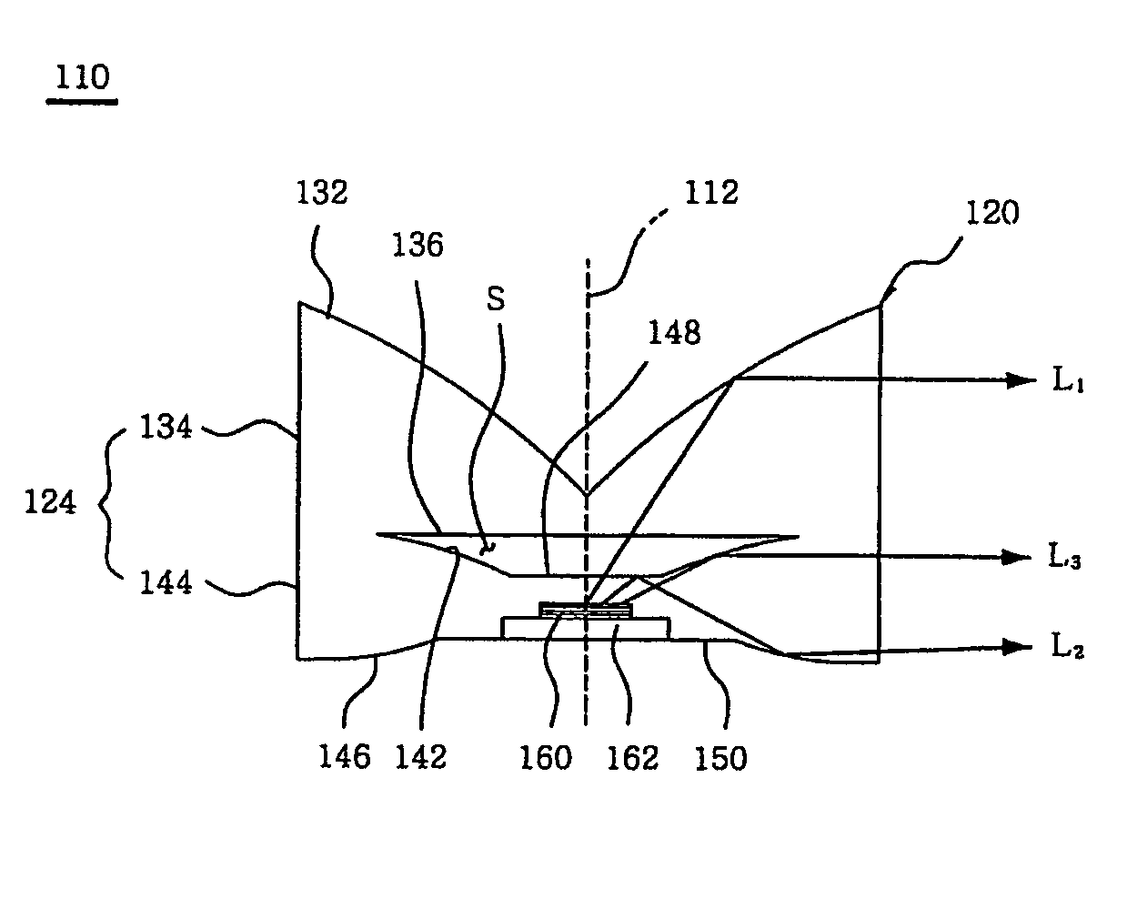
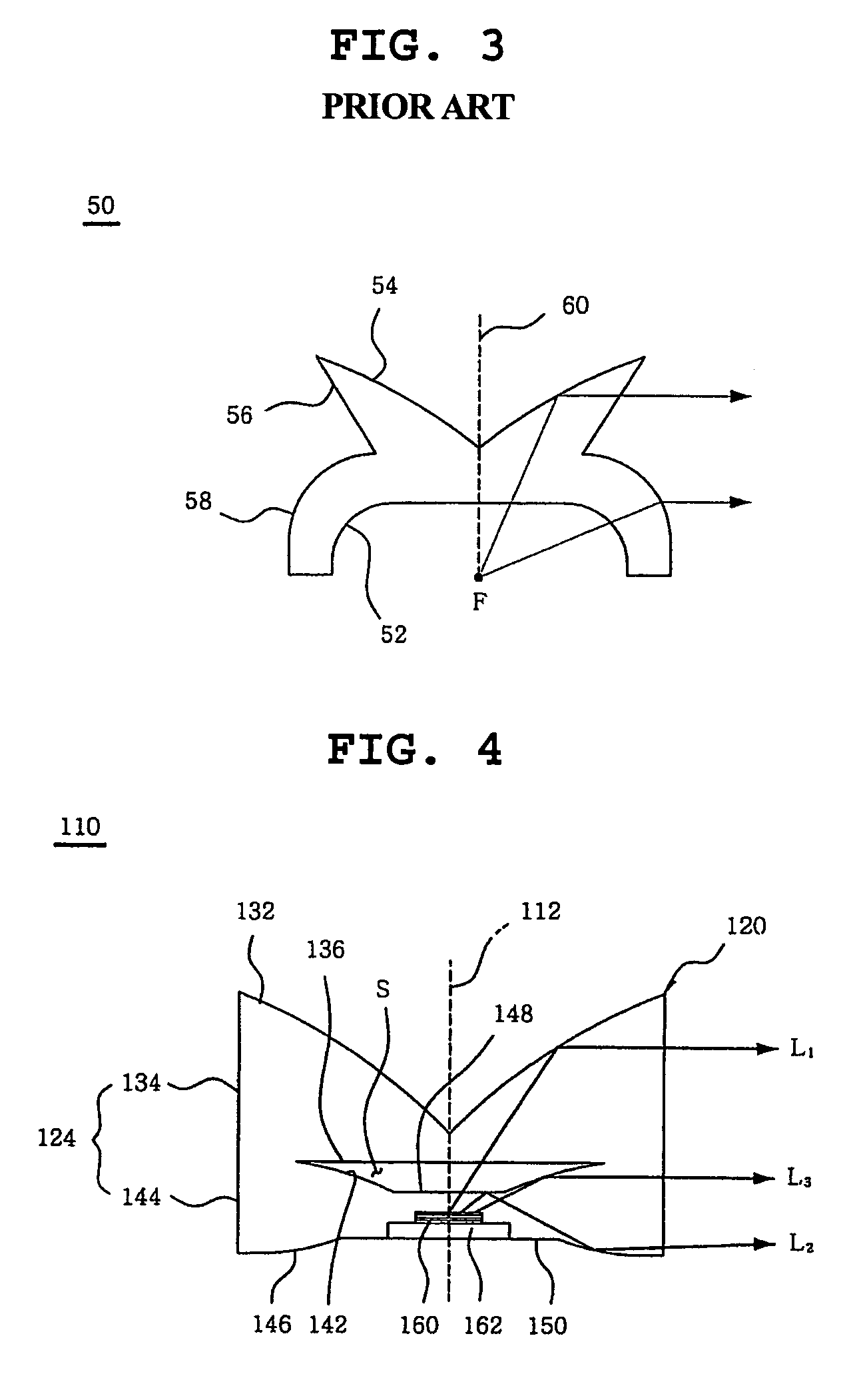
[0044]FIG. 4 is a sectional view of a lens 110 for LED light sources, according to an embodiment of the present invention. FIG. 5 is an exploded perspective view of the lens 110 of FIG. 4.

[0045]The lens 110 for LED light sources according to the present embodiment of the invention includes a lens body 120. The lens body 120 has a bottom surface 150, an upper reflective surface 132 which is symmetrical around a center axis 112 of the lens 110 and angled with respect to the center axis 112, and a side surface 124 which extends from an edge of the upper reflective surface 132 to an edge of the bottom surface 150. The lens 110 further includes an inner space (S) which is defined in the le...


PUM


Abstract

A lens for light emitting diode (LED) light sources which allows light emitted from an LED light source to exit the lens in a direction perpendicular to a vertical center axis of the lens. The lens of the present invention includes an inner space which is defined in a lens body having both a bottom surface and an upper reflective surface, so that light passing through the inner space is partially reflected by total internal reflection on a portion (selective transmission surface, inner reflective surface, inside reflective surface) of a boundary surface between the inner space and the lens body. Thus, light emitted from an LED light source efficiently exits the lens through a side surface. Accordingly, the lens of the present invention is used in efficient display and illumination optical systems.

Description

[0001]The present application claims priority under 35 U.S.C. §119 to Korean Patent Application No. 2004-82746 filed on Oct. 15, 2004. The content of the application is incorporated herein by reference in its entirety.BACKGROUND OF THE INVENTION[0002]1. Field of the Invention[0003]The present invention relates generally to lenses for LED (light emitting diode) light sources and, more particularly, to a lens for LED light sources which is used in efficient display and illumination optical systems.[0004]2. Description of the Related Art[0005]Recently, in display and illumination optical systems, the needs of light sources which are environmentally-friendly and highly efficient and have long life spans has increased greatly. To achieve the above-mentioned purpose, studies have been conducted to increase the efficiency and brightness of LEDs. Alternative light sources using LEDs have been developed. Such LED light sources are used in display and illumination optical systems. In particul...

Claims


Application Information

Patent Timeline
Patent Type & Authority Patents(United States)
IPC IPC(8): F21V5/00F21V5/04H01L33/58
CPCF21V5/04F21V7/0091G02B19/0071G02B19/0028G02B19/0061F21Y2101/02H01L33/58H01L33/60F21Y2115/10F21V17/10G03B21/14F21K9/69
Inventor KIM, JIN JONGJEONG, HO SEOPLEE, SANG HYUCKJUN, JOO HEE
Owner SAMSUNG ELECTRO MECHANICS CO LTD
Why Eureka
Try Eureka