Molded plastic elbow

a molded plastic and elbow technology, applied in the direction of bends, dough shaping, manufacturing tools, etc., can solve the problems of hydraulic pressure loss, fatigue, adversely restricting the terrain area which can be effectively irrigated,

Inactive Publication Date: 2006-12-26
ANTHONY MFG INDAL PRODS DIV
View PDF11 Cites 22 Cited by
  • Summary
  • Abstract
  • Description
  • Claims
  • Application Information

AI Technical Summary

Benefits of technology

[0007]In accordance with the invention, an improved molded plastic elbow and related mold assembly and production method are provided, wherein the elbow has an internal flow path defining a turn with a smoothly radiused inside surface. The elbow is formed by injecting plastic material into a mold cavity formed by closed mold members in cooperation with a pair of slidably retractable core units having distal ends in mating and angularly set end-to-end engagement to form the internal flow path. Each core unit comprises an outer core pin slidably supporting an inner slide segment on a ramped track, wherein the inner slide segment defines a curved inside edge to form a portion of the smoothly radiused inside turn in the molded part. Initial retraction of the outer core pin of each core unit from the mold cavity permits relative displacement of the associated inner slide segment along the ramped track in a direction toward a centerline of the flow path, sufficiently to clear the radiused inside turn in the molded part and thereby permit interference-free linear sliding retraction of the core unit from the molded plastic part.
[0010]When the outer core pin of each core unit is retracted from the mold cavity, following injection forming of the molded elbow therein, the actuator means associated with each inner slide segment accommodates advancing or forward relative displacement of the inner slide segment along the ramped track. Such advancing displacement is accompanied by an outward shift in the position of the inner slide segment in a direction toward the centerline of the flow path in the molded part. This outward shift by the inner slide segment carries the curved inside edge thereof to a position spaced slightly from the curved inside turn of the flow path formed in the molded part, so that the entire core unit can be longitudinally and linearly retracted from the molded part without interference.

Problems solved by technology

Unfortunately, this standard molding apparatus and related process has necessarily limited the inside edge geometry of the internal flow path to a relatively sharp corner in order to permit interference-free linear retraction of the sliding core units from the molded part.
This sharp-cornered geometry undesirably contributes to substantial hydraulic pressure loss as water flows through the elbow fitting.
As a result, especially in an irrigation network including a substantial number of such elbow fittings, the cumulative pressure loss attributable to the elbow fittings can adversely restrict the terrain area which can be effectively irrigated.
Moreover, the relatively sharp inside edge geometry represents a stress concentration site which is susceptible to fatigue cracking in response to on-off pressure cycling over a period of time.
Similarly, hydraulic pressure losses and fatigue problems have been noted in other molded plastic elbow-type fluid conduits, such as, for example, in the inlet and outlet portions of molded plastic valve bodies such as typical anti-syphon and pressure and flow regulating irrigation control valves.

Method used


Image

  • Molded plastic elbow
  • Molded plastic elbow
  • Molded plastic elbow

Examples


Embodiment Construction

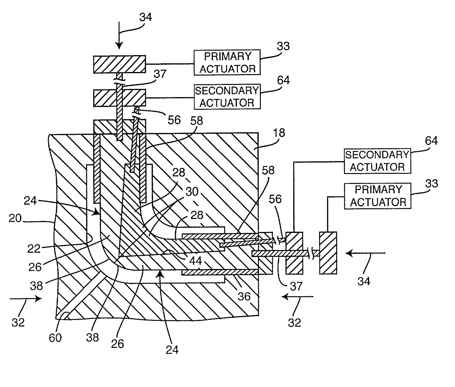
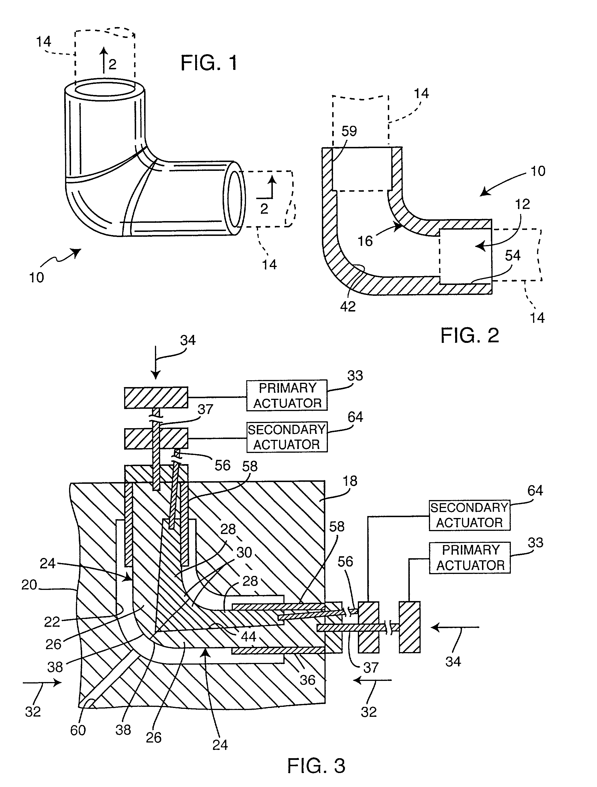
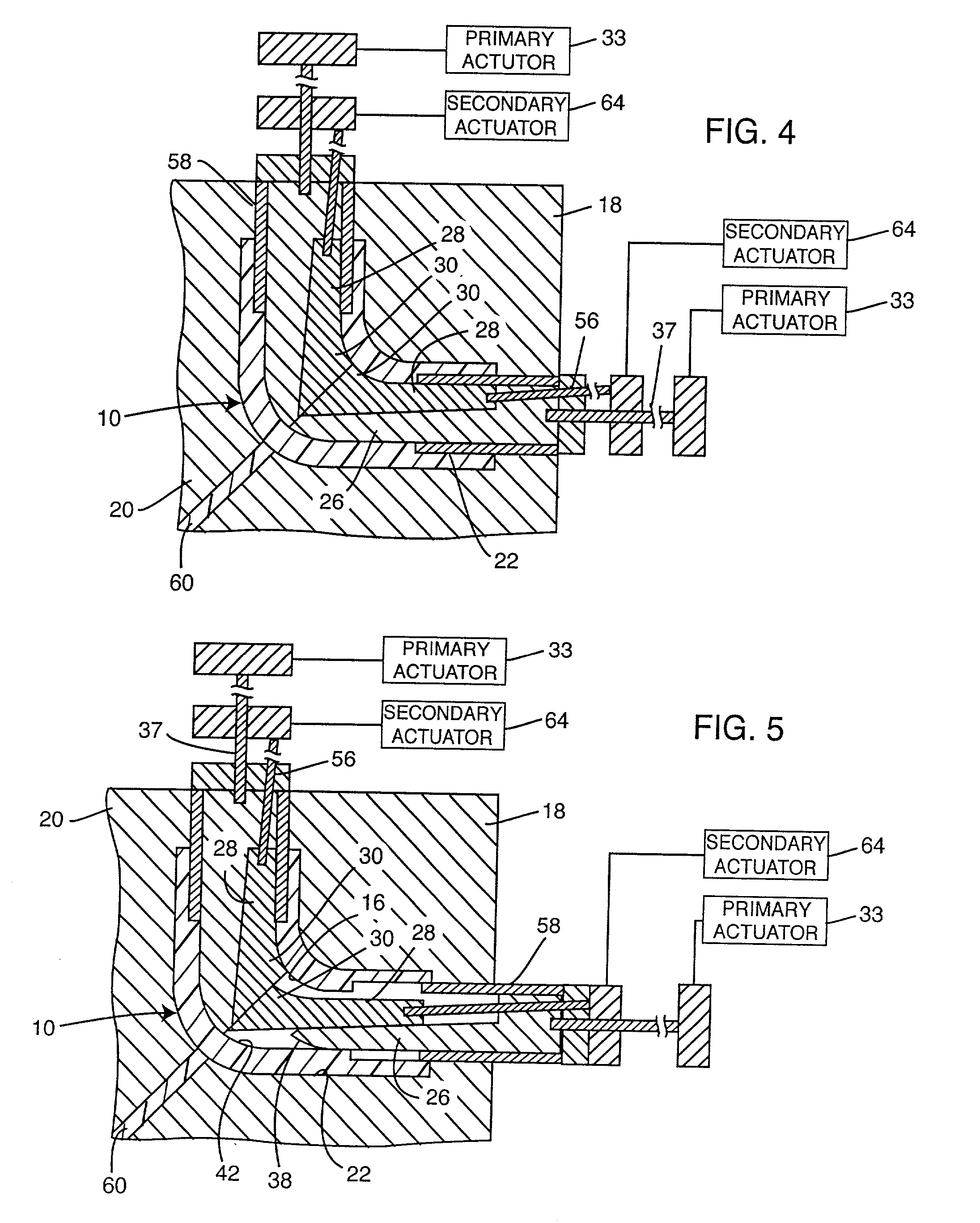
[0024]As shown in the exemplary drawings, the present invention relates to an improved molded plastic elbow, in this instance a new and improved molded plastic elbow fitting referred to generally in the accompanying drawings by the reference numeral 10, and a related molding assembly and method for producing the improved elbow and fitting. As shown in FIGS. 1 and 2, the elbow fitting 10 comprises a unitary or one-piece tubular element formed from molded plastic to define an internal flow path 12 (FIG. 2) having a turn formed along the length thereof. The elbow fitting 10 comprises a plumbing connector for coupling fluid flow such as water or the like between a pair of pipes 14 (shown in dotted lines in FIGS. 1 and 2)

[0025]The improved elbow fitting 10 of the present invention is particularly designed to form the internal flow path 12 with a smoothly radiused inside turn, as identified by reference numeral 16 in FIG. 2. In this regard, molded plastic elbow fittings of this general ty...


PUM

PropertyMeasurementUnit
angleaaaaaaaaaa
angleaaaaaaaaaa
shapeaaaaaaaaaa

Abstract

An improved molded plastic elbow and a related mold assembly and manufacturing method are provided, wherein the elbow defines an internal flow path having a smoothly radiused inside turn. The elbow is formed by injecting plastic material into a tubular mold cavity formed by closed mold members in cooperation with a pair of slidably retractable core units of circular cross section and having distal ends in mating, angularly set end-to-end contact to form the internal flow path having a turn formed along the length thereof. Each core unit comprises an outer core pin to form an outer portion of the flow path and including a ramped track for slide-fit mounting of an inner slide segment which forms an inner portion of the flow path and further includes a curved inside edge to form a portion of the smoothly radiused inside turn. Initial retraction of each outer core pin from the mold cavity permits relative advancement of the inner slide segment along the ramped track toward a centerline of the flow path, sufficiently for the curved inside edge of the inner slide segment to clear the radiused inside turn of the molded elbow and thereby enable interference-free linear withdrawal of the core unit from the molded plastic part.

Description

[0001]This is a divisional of U.S. application Ser. No. 09 / 487,153, filed Jan. 19, 2000.BACKGROUND OF THE INVENTION[0002]This invention relates generally to improvements in molded plastic pipe components of the type typically found in irrigation sprinkler systems and the like. More specifically, this invention relates to an improved molded plastic elbow and to a related mold assembly and method for producing the elbow with an internal flow path defining a turn, wherein the inside edge of the turn is smoothly radiused for reduced hydraulic pressure loss and to provide the elbow with improved fatigue resistance.[0003]Plastic pipe and related molded plastic pipe fittings are well known in the art for use in a variety of relatively low to mid-range fluid pressure applications, particularly such as in irrigation sprinkler systems to deliver irrigation water under pressure to sprinkler devices having appropriate spray nozzles or the like to distribute the water over a prescribed terrain a...

Claims


Application Information

Patent Timeline
Patent Type & Authority Patents(United States)
IPC IPC(8): B29C45/40B29C45/26F16L43/00
CPCB29C45/2614F16L43/00F16L43/008B29L2031/243Y10T428/139Y10S425/058Y10T428/1352
Inventor EVANS, DAVID V.ENSWORTH, MARK M.
Owner ANTHONY MFG INDAL PRODS DIV
Why Eureka
Try Eureka