
Product labelling

a product label and label technology, applied in the direction of process and machine control, mechanical control devices, instruments, etc., can solve the problems of not being able to quickly extend the head, not being able to detect the product, and not being able to identify the produ

Inactive Publication Date: 2006-12-26
2502851 ONTARIO LTD
View PDF13 Cites 9 Cited by
  • Summary
  • Abstract
  • Description
  • Claims
  • Application Information

AI Technical Summary

Benefits of technology

"The present invention is a product labelling apparatus that uses an imager to identify a portion of a product that will pass through a target area of a labeller. The processor then tracks the progress of the product and controls the labeller to label the target area when the product reaches it. The apparatus can also filter the image to identify the colors of the products and use groups of blobs to select the correct labeller. The technical effect of this invention is to provide a more efficient and accurate method for labeling products."

Problems solved by technology

This approach, however, is only well suited for labelling products of uniform dimensions.
However, when the head reaches the labelling station, it is coupled to the positive pressure plenum which causes the head to rapidly extend until it tamps a product below.
A drawback with this approach is that products may not be present in each of the tray cups.
A further drawback is that some types of products, such as vine ripened tomatoes, may have obstructions (the vines) which may end up being labelled rather than the product itself.

Method used


Image

  • Product labelling
  • Product labelling
  • Product labelling

Examples


Embodiment Construction

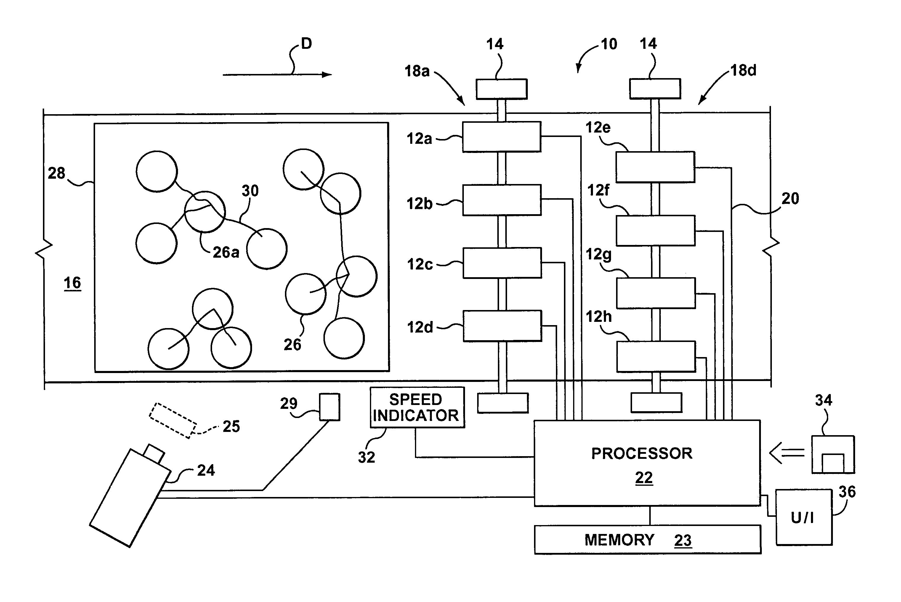
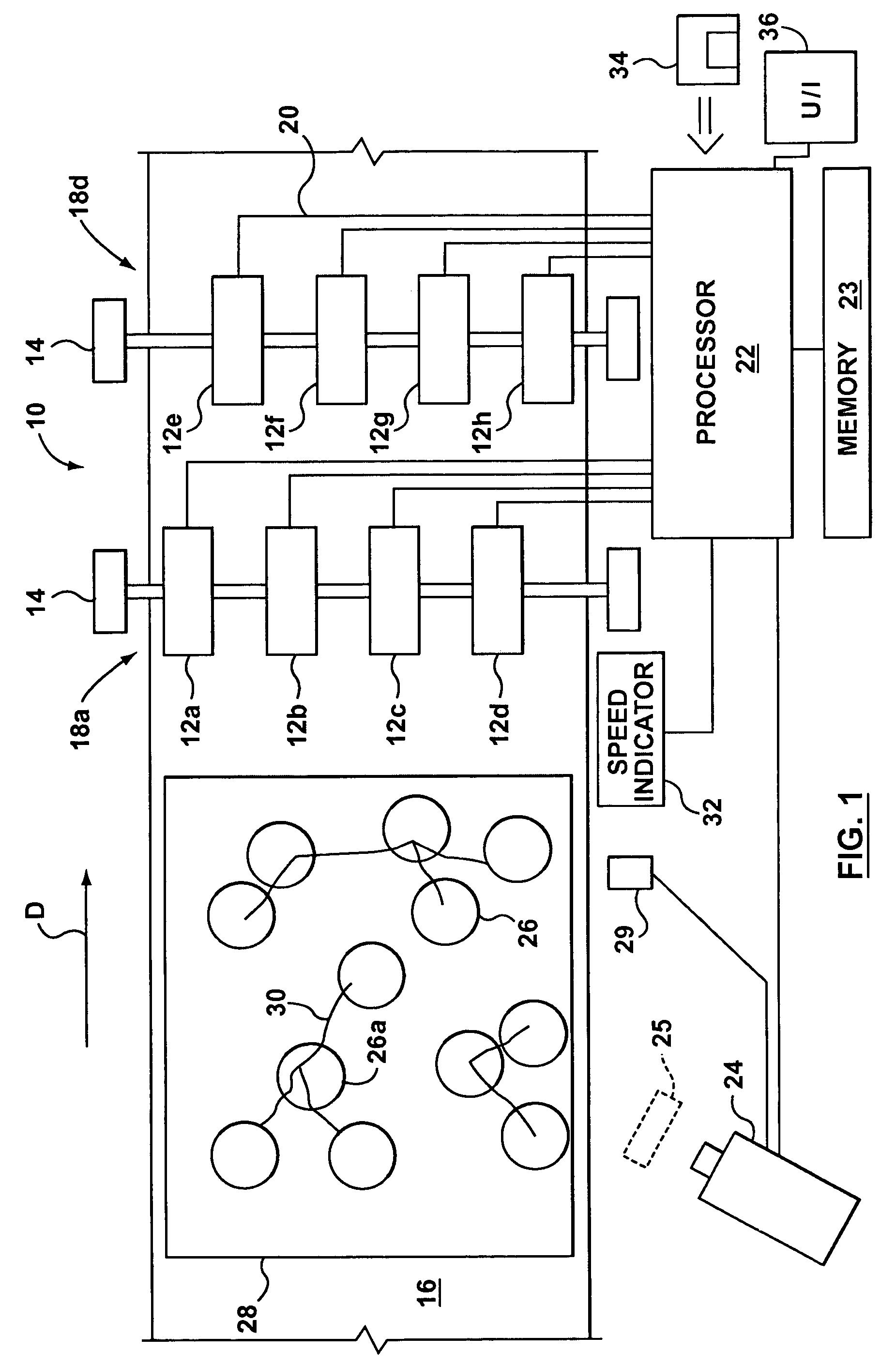
[0018]Turning to FIG. 1, a labelling apparatus 10 comprises labellers 12a to 12h (referred to individually as labellers 12) mounted by mounts 14 at a fixed position above a conveyor 16, which moves in a downstream direction D. The labellers 12 are arranged as an upstream bank 18u of labellers (12a to 12d) and a downstream bank 18d of labellers (12e to 12h). Each bank 18u, 18d of labellers extends transversely of the conveyor 16. The labellers in a bank are equally spaced and the labellers of the downstream bank 18d are offset from those of the upstream bank 18u so that each labeller has a different transverse position over the conveyor. Further, the labellers 12 extend substantially across the width of the conveyor so as to provide eight distinct transverse positions across the conveyor. The labellers 12 are operatively connected to a processor 22 on paths 20. The processor has an associated memory 23 and user interface 36. Memory 23 is loaded with software so that the processor may...


PUM

PropertyMeasurementUnit
areaaaaaaaaaaa
field of viewaaaaaaaaaa
colouraaaaaaaaaa

Abstract

A product labeling apparatus has a plurality of labelers, an imager for imaging products; and a processor responsive to an output of the imager and operatively connected to a control input of each of the labelers. The processor processes an image received from the imager to identify a portion of a product which portion will pass a target area of a given labeller. The processor then tracks progress of that portion of the product and controls an appropriate one of the labelers to label the portion of the product when that portion of the product is at the target area of the given labeler.

Description

BACKGROUND OF INVENTION[0001]This invention relates to product labelling.[0002]Products to be sold are commonly labelled. In this regard, automatic labelling apparatus may be employed where the products are smaller and processed in large volumes. One approach in this regard is to wipe a label onto each product as its passes a labelling head. This approach, however, is only well suited for labelling products of uniform dimensions. Where products have irregular dimensions, such as agricultural produce, the distance between a given product and the labelling head will vary. To label such products, tamping labellers are typically used. U.S. Pat. No. 6,257,294 to Weisbeck discloses a tamping labeller. In Weisbeck, a turret carries a number of reciprocating pick up heads about its periphery. The turret has a vacuum plenum and a positive pressure plenum. The turret rotates each head, consecutively, to a labelling station. A head normally communicates with the vacuum plenum which keeps it in...

Claims


Application Information

Patent Timeline
Patent Type & Authority Patents(United States)
IPC IPC(8): B65C3/00B65C9/06B65C9/40B65C9/42
CPCB65C3/00B65C9/40Y10T156/17Y10T156/171Y10T156/1702
Inventor SLEIMAN, JOSEPH Z.ZHAO, FEIPENGNIELSEN, PETER C.
Owner 2502851 ONTARIO LTD
Learn More