Method and apparatus for blow-molding an article having a solid radially outwardly projecting flange

a technology of radially outwardly projecting flanges and blow molding processes, which is applied in the direction of transportation and packaging, other domestic articles, rigid containers, etc., can solve the problems of inability to use seal-on membranes or seamed-on metal end closures for such containers, undesirable top ends, and inability to meet the requirements of the post-mold finishing process. , the post-mold finishing process is relatively complicated and costly

Inactive Publication Date: 2006-12-26
SONOCO DEV INC
View PDF46 Cites 10 Cited by
  • Summary
  • Abstract
  • Description
  • Claims
  • Application Information

AI Technical Summary

Problems solved by technology

In some applications, such top ends are undesirable because of the nature of the contents of the container, which in some cases may require wide-mouth openings to facilitate getting the contents into and out of the container.
However, it has not been practical or cost-effective to employ seal-on membranes or seamed-on metal end closures for such containers because the blow-molding process has not allowed for easily making the type of flat, outwardly extending flanges required for such closures.
This post-mold finishing process is relatively complicated and costly.
As noted, the post-mold finishing operations are relatively costly.
It has been found, however, that it can be difficult to completely fill the groove when the radial length of the groove is relatively large in comparison with the axial width of the groove (i.e., when the flange is long and thin).

Method used


Image

  • Method and apparatus for blow-molding an article having a solid radially outwardly projecting flange
  • Method and apparatus for blow-molding an article having a solid radially outwardly projecting flange
  • Method and apparatus for blow-molding an article having a solid radially outwardly projecting flange

Examples


Embodiment Construction

[0017]The present inventions now will be described more fully hereinafter with reference to the accompanying drawings, in which some but not all embodiments of the invention are shown. Indeed, these inventions may be embodied in many different forms and should not be construed as limited to the embodiments set forth herein; rather, these embodiments are provided so that this disclosure will satisfy applicable legal requirements. Like numbers refer to like elements throughout.

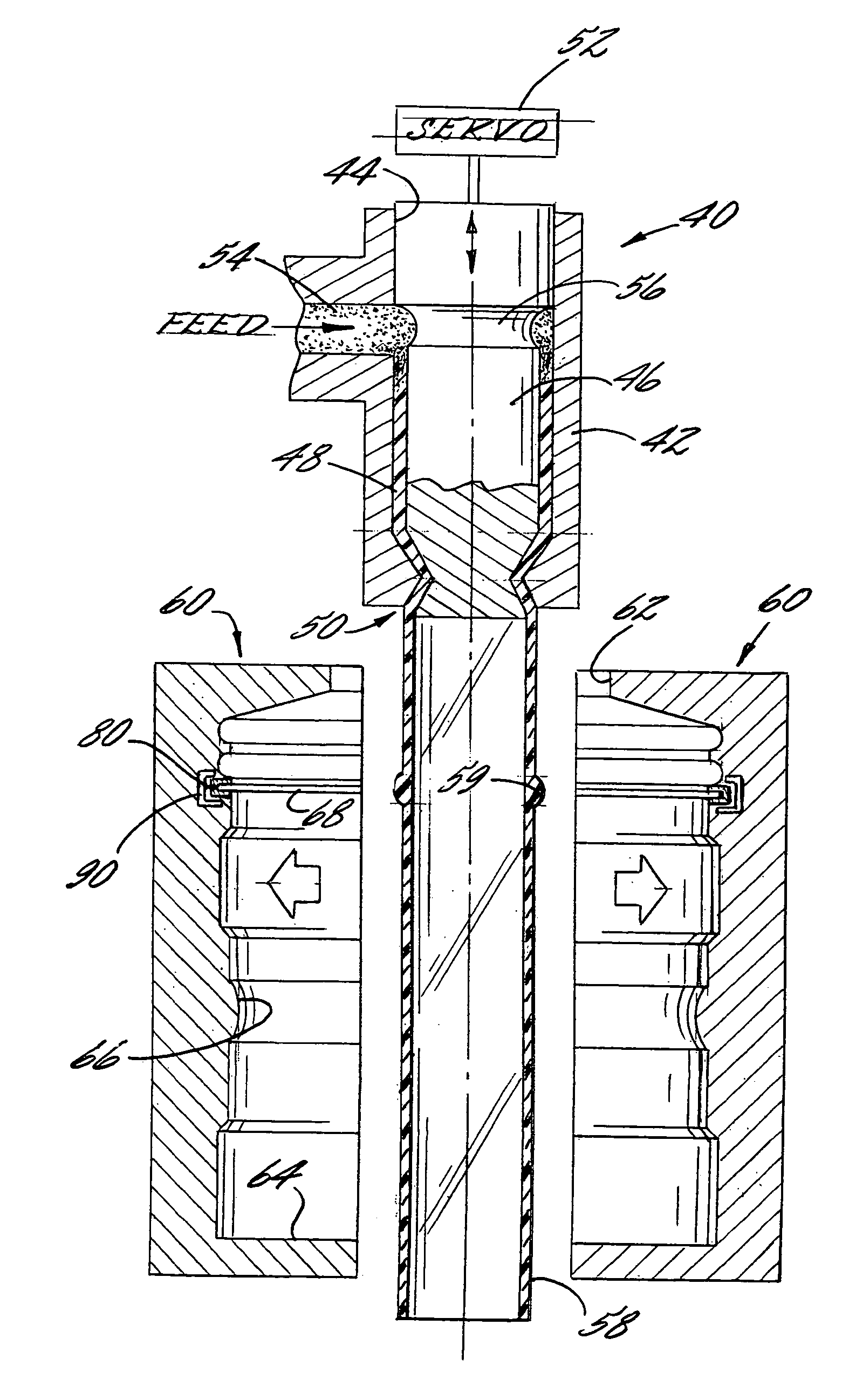
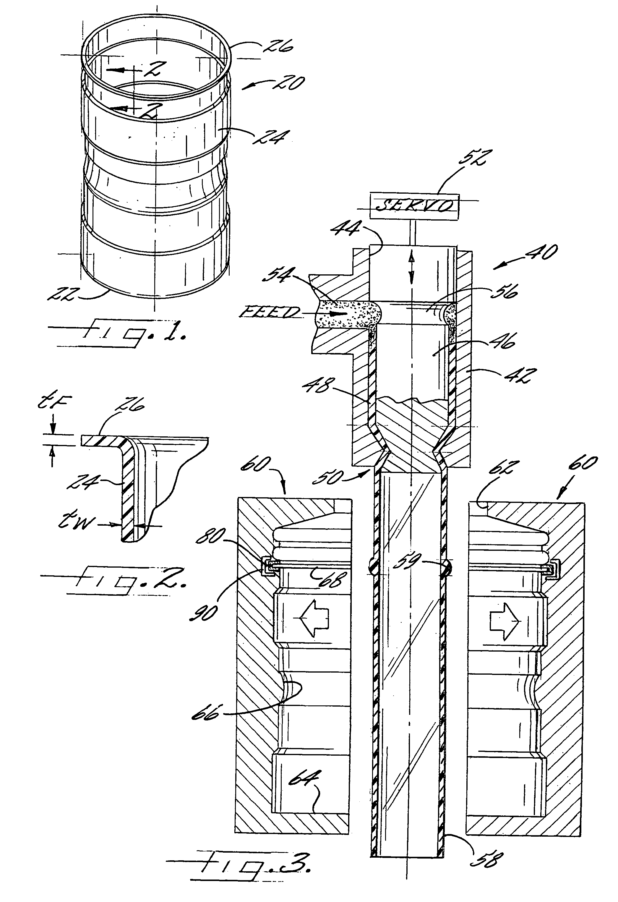
[0018]FIG. 1 shows a blow-molded container 20 in accordance with one embodiment of the invention. The container comprises a base wall 22, and a tubular side wall 24 whose bottom end is joined with the base wall. In the illustrated embodiment, the side wall 24 has a circular cross-section and includes several sections of different diameters and shapes to impart an aesthetically pleasing appearance to the container. However, it will be recognized that blow-molded articles can be made to have various cross-sectiona...


PUM

PropertyMeasurementUnit
temperatureaaaaaaaaaa
diameteraaaaaaaaaa
thicknessaaaaaaaaaa

Abstract

A solid outwardly projecting flange is formed on the side wall of a blow-molded article by providing a blow mold having a circumferential groove that is filled by flowable thermoplastic during a blow cycle. The mold includes a heating system locally disposed adjacent the groove for heating the walls of the groove so as to heat the thermoplastic in this region, thereby reducing the viscosity of the thermoplastic so that it more-readily flows into and completely fills the groove. The mold can also include a cooling system disposed locally adjacent the groove for cooling the flange of the blow-molded article prior to ejection of the article from the mold.

Description

CROSS-REFERENCE TO RELATED APPLICATION[0001]This application is a continuation-in-part of application Ser. No. 10 / 224,101, filed Aug. 20, 2002, now abandoned, which is currently pending and is hereby incorporated herein by reference.BACKGROUND OF THE INVENTION[0002]The invention relates to blow molding processes and to apparatus for making blow-molded articles.[0003]Conventional blow-molded containers generally have small-diameter top ends that are threaded to accept screw-on caps. In some applications, such top ends are undesirable because of the nature of the contents of the container, which in some cases may require wide-mouth openings to facilitate getting the contents into and out of the container. Thus, alternative closures such as seal-on membranes or seamed-on metal closures would be desirable in many cases.[0004]However, it has not been practical or cost-effective to employ seal-on membranes or seamed-on metal end closures for such containers because the blow-molding proces...

Claims


Application Information

Patent Timeline
Patent Type & Authority Patents(United States)
IPC IPC(8): B29C49/64B29C49/00B29C49/04B29C49/48B29C49/50B29C69/00B65D1/10B65D1/12B65D1/40
CPCB29C49/0078B29C49/4278B29C49/4823B65D1/10B65D1/12B65D1/40B29C49/04B29C49/50B29C2793/009B29L2031/716B29B2911/14326B29B2911/1442B29C2949/072B29C2949/077B29C2949/074B29C2949/0721
Inventor CLOUGHERTY, KENAN J.
Owner SONOCO DEV INC
Why Eureka
Try Eureka