Electrical connector with snap fit retainer ring constructed to enhance the connection of the connector to an electrical box

a technology of snap-fit retainer and connector, which is applied in the direction of insulated conductors, cable connections, coupling devices, etc., can solve the problems of affecting the service life of the connector, and requiring a considerable amount of force to deflect the connector, etc., to achieve the effect of reducing the amount of force required

Active Publication Date: 2006-12-26
BRIDGEPORT FITTINGS LLC
View PDF59 Cites 38 Cited by
  • Summary
  • Abstract
  • Description
  • Claims
  • Application Information

AI Technical Summary

Benefits of technology

[0012]Another object of this invention is to provide for an electrical connector assembly that includes an electrical connector body having an outlet end with a frustro-conical outer surface having a complementary frustro-conical retaining ring that is readily fitted to and retained on the outlet end portion of the connector body.
[0041]A still further embodiment of the invention utilizes a modified connector body provided with a frustro conical outlet end having a frustro conical shaped external snap fit retaining ring by which the connector assembly can be readily attached to an electrical panel or electrical box by a snap fit, and having a uniquely formed wire retainer device that clips onto the inlet end of the connector body and is externally secured to the connector body for enhancing ease of assembly while providing the wire retainer to extend into the inlet end of the connector body with sufficient flexibility and range of movement for retaining a wire conductor or conductor sheath within the connector body in a manner to prohibit any unintentional separation of the wire conductor or sheath from the connector body.

Problems solved by technology

While such “snap fit” connectors have been in use for some time, the attachment of such “snap-fit” connectors to an electric box require the application of a considerable amount of force to deflect the locking tangs in order to push or pull the connector and retainer ring through a knock-out hole of an electric box.
Frequently, an installer or user may not have sufficient access necessary to apply the necessary force to manually pull the leading end of the connector assembly through the knockout hole due to the relative rigid flexibility of the locking tangs in order to seat and lock the connector assembly to the knockout opening.
Applying such pulling force directly on the wires to lock a snap-fit connector assembly to an electric box could seriously damage the conducting wires.

Method used


Image

  • Electrical connector with snap fit retainer ring constructed to enhance the connection of the connector to an electrical box
  • Electrical connector with snap fit retainer ring constructed to enhance the connection of the connector to an electrical box
  • Electrical connector with snap fit retainer ring constructed to enhance the connection of the connector to an electrical box

Examples


Embodiment Construction

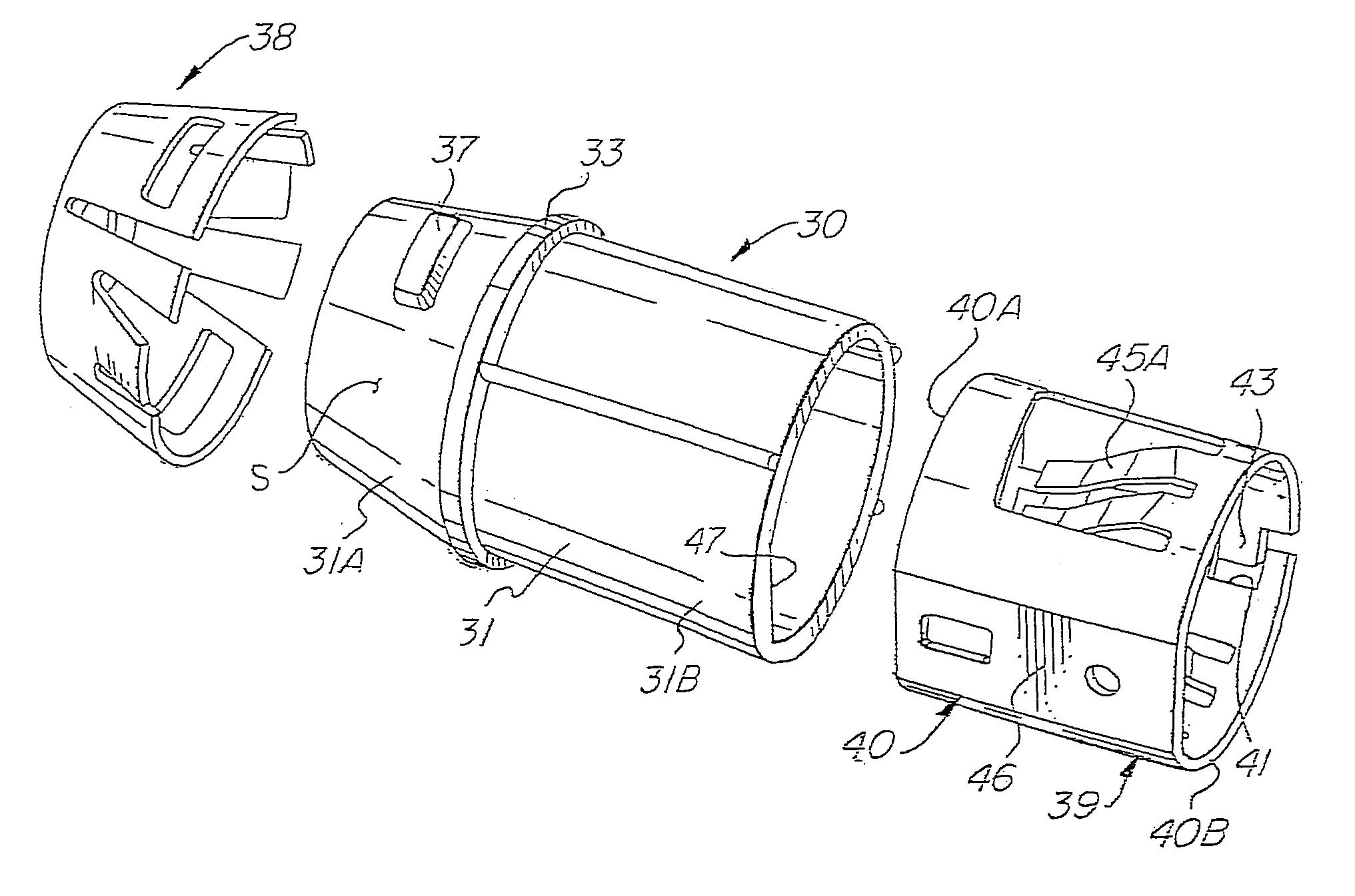
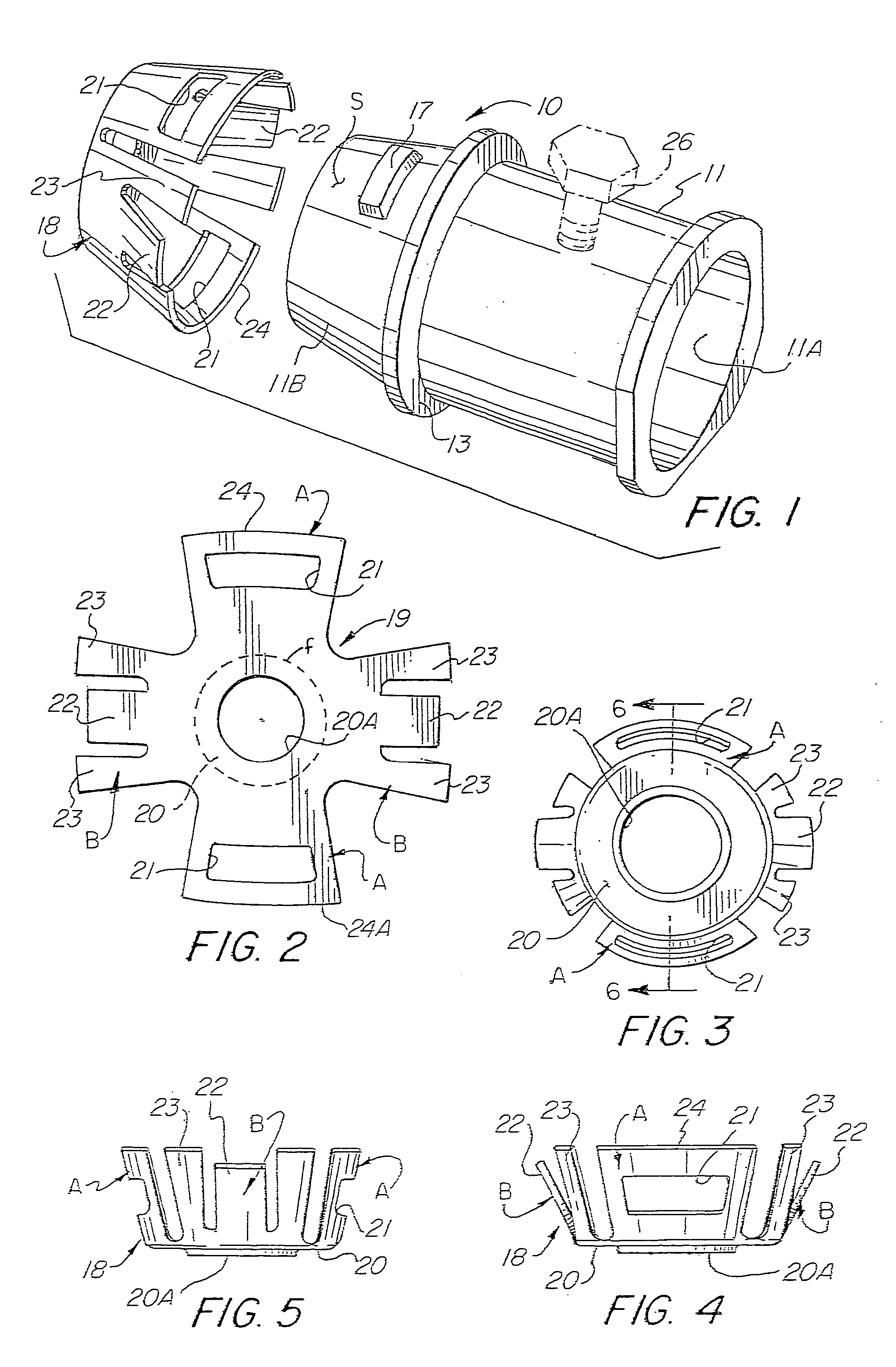
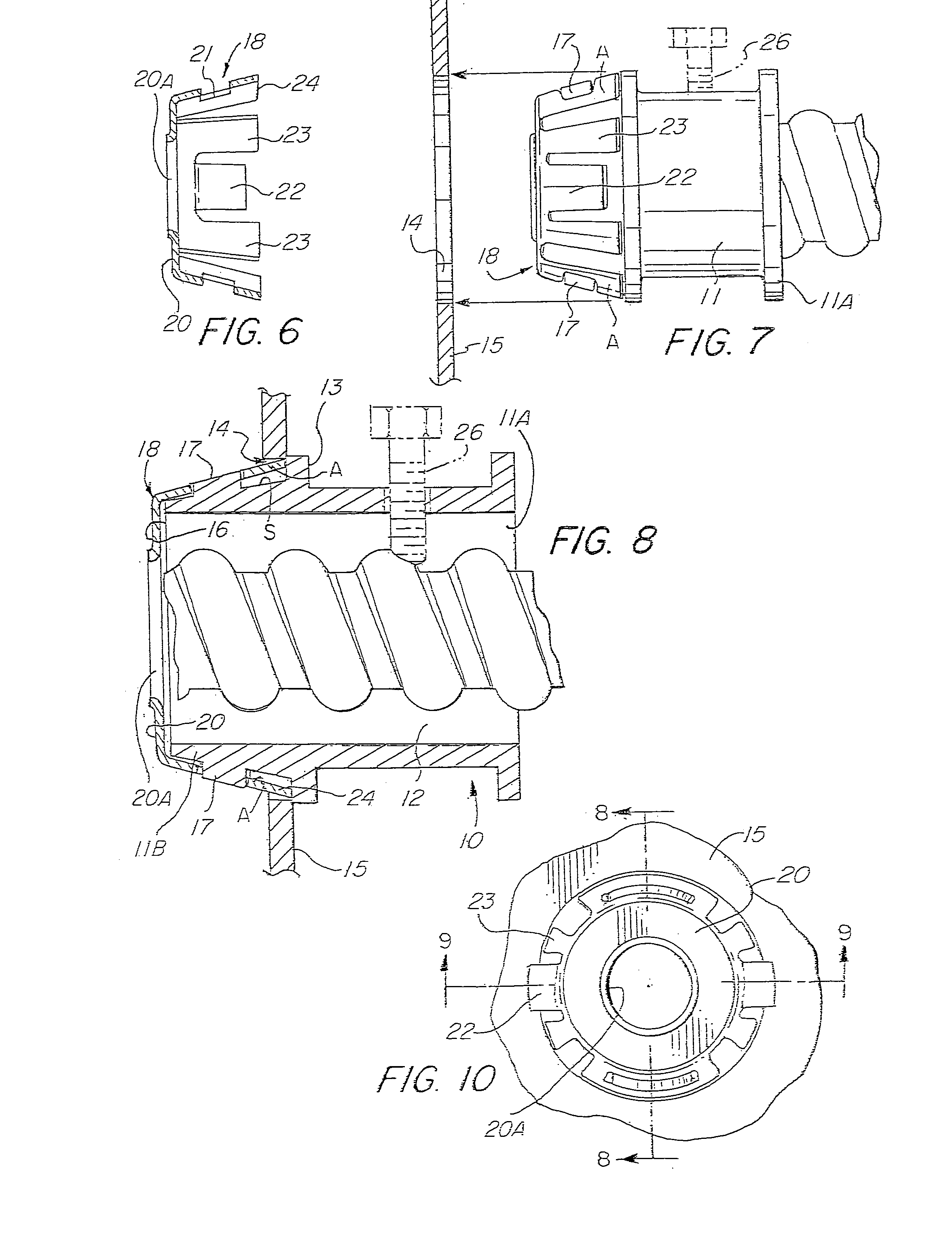
[0108]Referring to the drawings, there is shown in FIG. 1 an electrical connector assembly 10. The connector assembly 10 includes a connector body 11, which is usually formed of metal casting, e.g. zinc or other suitable metallic alloy. The connector body 11 is formed with an inlet end portion 11A and an outlet end portion 11B and having a bore 12 extending therethrough. Intermediate the connector body 11 or between the inlet end portion 11A and outlet end portion 11B there is provided a radially outwardly extending flange 13 which functions as a stop to limit the amount that the connector body 11 may be inserted through the knockout hole 14 of an electric box 15, as noted in FIG. 8.

[0109]As shown in FIGS. 1 and 8, the outer surface S of the outlet end portion 11B slopes, tapers or converges toward the outlet opening 16 whereby the outer surface S of the outlet end portion 11B has a generally frustro-conical configuration. Formed on the surface S of the outlet end portion 11B is an ...


PUM


Abstract

An electric connector assembly disclosing various embodiments, each of which includes a connector body having a frustro-conically shaped outlet end portion that converges toward the outlet opening and having a complementary frustro conically shaped retainer ring circumscribing the outlet end portion wherein the retainer ring is integrally formed with a locking tang and ground tangs arranged to be snap fitted to a knock-out hole of an electric box. The latest embodiment includes a frustro-conical retainer ring having an auxiliary tang arranged to permit the connector assembly to be obliquely inserted and locked to a knock-out hole of an electric box using a minimum of applied force for effecting a snap fit connection to both lock and electrically ground the connector assembly to the electric box and a method of installing the associated connector body to an electric box.

Description

RELATED APPLICATIONS[0001]This application is a continuation in part application of a continuation in part application of application Ser. No. 11 / 364,435 filed Feb. 28, 2006 for Snap-Fit Electrical Connector Assembly For Facilitating The Connection of the Electric Connector Assembly To An Electric Box, which is a continuation in part of application Ser. No. 11 / 258,990 filed Oct. 26, 2005 now U.S. Pat. No. 7,057,107, which is a continuation in part of application Ser. No. 11 / 151,374 filed Jun. 13, 2005 now U.S. Pat. No. 7,075,007 for Snap Fit Electrical Connector Assembly With conical Outer Snap Fit Retainer And One Or More Internal Snap Fit Wire Retainers, which is a continuation in part of application Ser. No. 11 / 100,250 filed Apr. 6, 2005 now U.S. Pat. No. 7,064,272 for Snap In Electrical Connector Assembly With Unidirectional Wire Conductor Retainer Ring, which is a continuation in part application of application Ser. No. 10 / 939,619 filed Sep. 13, 2004 for Electrical Connector Wi...

Claims


Application Information

Patent Timeline
Patent Type & Authority Patents(United States)
IPC IPC(8): H02G3/00
CPCH01R4/646H01R13/741H02G3/0683H02G3/0691H01R4/36H01R43/26
Inventor AURAY, DELBERTKIELY, KENNETH M.
Owner BRIDGEPORT FITTINGS LLC
Why Eureka
Try Eureka