Method and arrangement for coupling messages in a central control device with decentralized communications devices

Inactive Publication Date: 2006-12-26
SIEMENS AG
View PDF6 Cites 2 Cited by
  • Summary
  • Abstract
  • Description
  • Claims
  • Application Information

AI Technical Summary

Benefits of technology

[0010]In one embodiment of the invention, the time-critical message traffic is ensured in a particularly advantageous way by an especially suitable communication protocol on just one partial connection link. On a further partial connection, in particular a long-distance connection, another, specifically suitable, communication protocol can then be used. This advantageously achieves the effect that already existing modules in decentralized devices can continue to be used, without the length of the connecting lines to a central control device being subject to restrictions. Similarly, the message transport is advantageously optimized, because the messages are just transported directly and so there is no longer the additional computational effort which would arise when one protocol is packed into another protocol. Similarly, fewer data therefore have to be transmitted, whereby time advantages and higher data capacities in message transport are attainable.
[0024]The message processing takes place advantageously in the second central device, because in this way previously customary peripheral devices can also be involved in the message control sequence, so that a mixture of previously customary devices of a private branch exchange with novel devices of a new private branch exchange can be operated and controlled in any desired form. In another embodiment of the invention, control messages for the connection control of a switching unit are generated advantageously in the central control device and transmitted to the second decentralized communication devices, or are used for controlling the switching unit in the case of mixed arrangements. In this way, connections can be established in the entire area of the switching device, irrespective of whether the communication subscribers are connected to novel devices or to customary devices.

Problems solved by technology

Consequently, such devices are not particularly well suited for flexible adaptation to growing numbers of subscribers.
Moreover, in the case of current devices, the setting-up of a communication infrastructure in the form of a network of decentralized devices which are supplied with messages by a central control is restricted because strict time requirements have to be satisfied when transporting control messages and, as from a defined length of the control line, it is no longer possible to comply with them.
If HDLC connections were simply lengthened, the time requirements between the communication partners involved at the end of the link cannot be satisfied.
This is not practicable, since many possible communication partners are concerned and consequently great expenditure is incurred and the communication partners would have to be provided with more resources, for example memories.
In the case of such a center-oriented configuration, problems arise because the data to be transported have to be fed to the central device ZE1.
Such a centrally oriented arrangement also gives rise to high expenditure on cabling, because both the control lines and the communication lines have to be routed to the central device ZE1.
It is not possible for peripheral devices to be distributed over a wide area, because the time-critical message traffic via the control lines with the aid of a HDLC protocol cannot take place over links comprising lines of any desired length.
Such private branch exchanges also cannot be modularly expanded to whatever extent is desired, because the switching unit MTS for example can only be provided as a complete unit.
The transmission rate in such systems is limited for example by the possibility that only a maximum of 64 kbits, or some other administratively fixed or technically dictated volume of data which is prescribed by the ISDN standard, can be transmitted per time slot.
In this case, different data rates for individual communication connections are not possible.

Method used


Image

  • Method and arrangement for coupling messages in a central control device with decentralized communications devices
  • Method and arrangement for coupling messages in a central control device with decentralized communications devices
  • Method and arrangement for coupling messages in a central control device with decentralized communications devices

Examples


Embodiment Construction

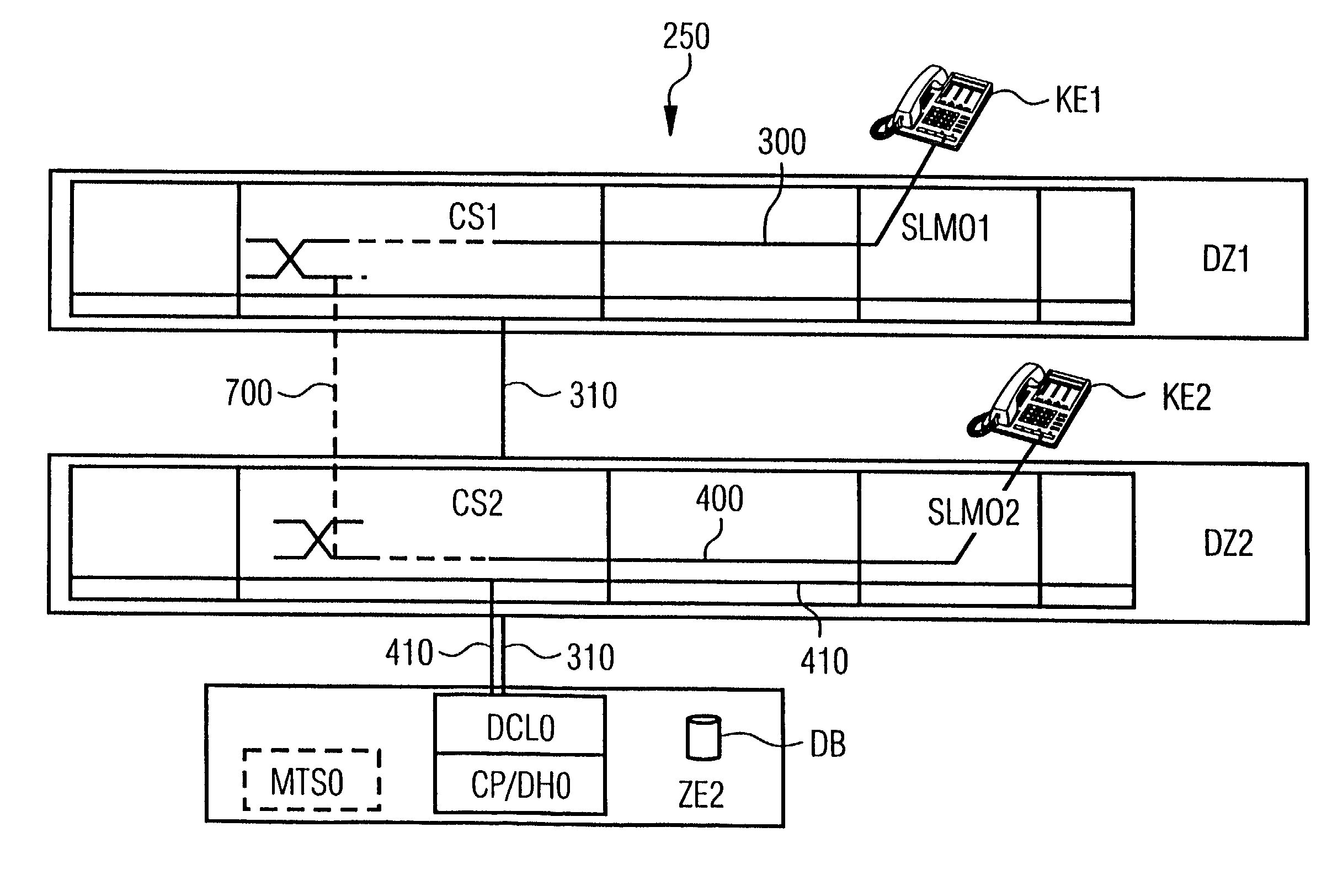
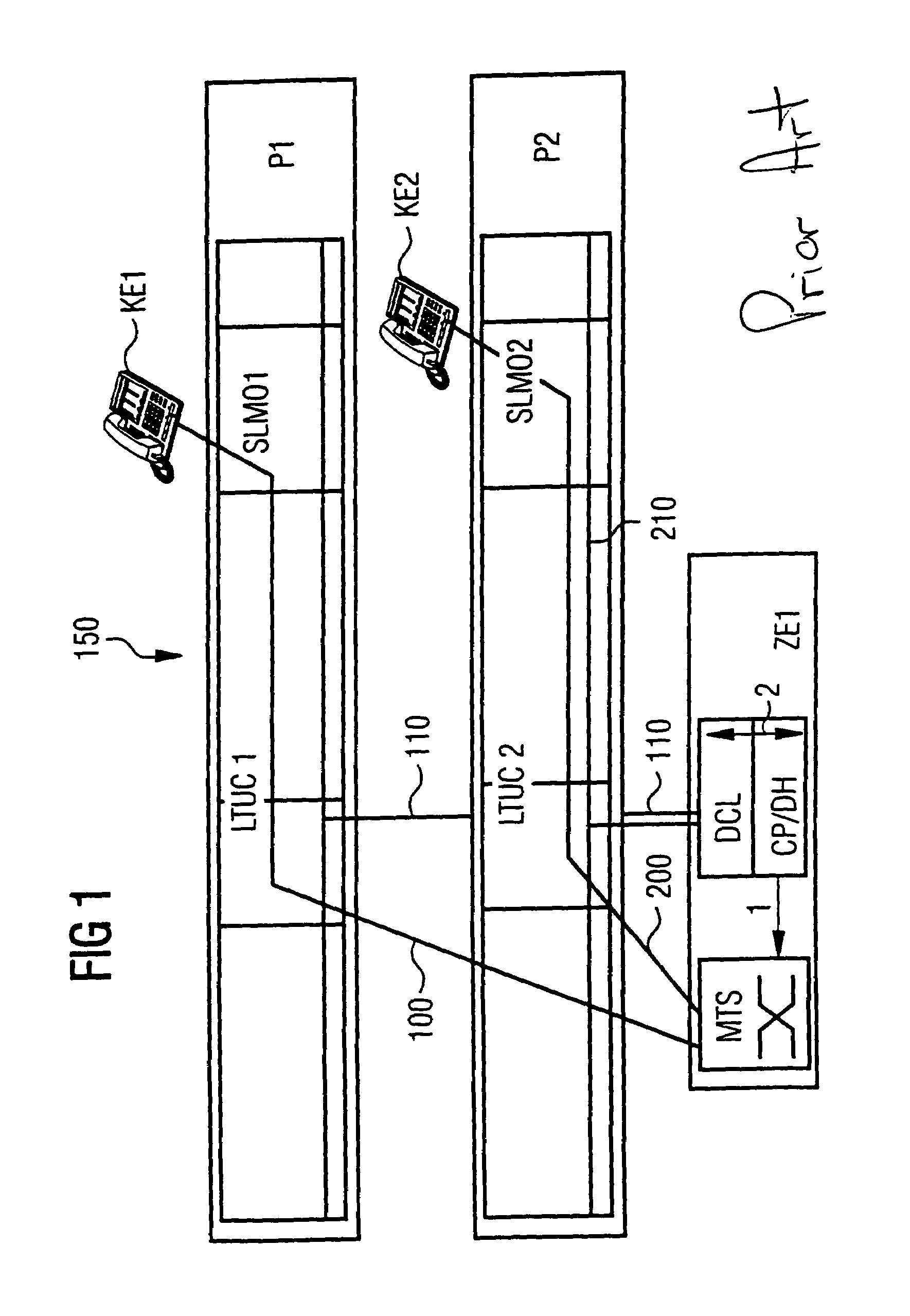
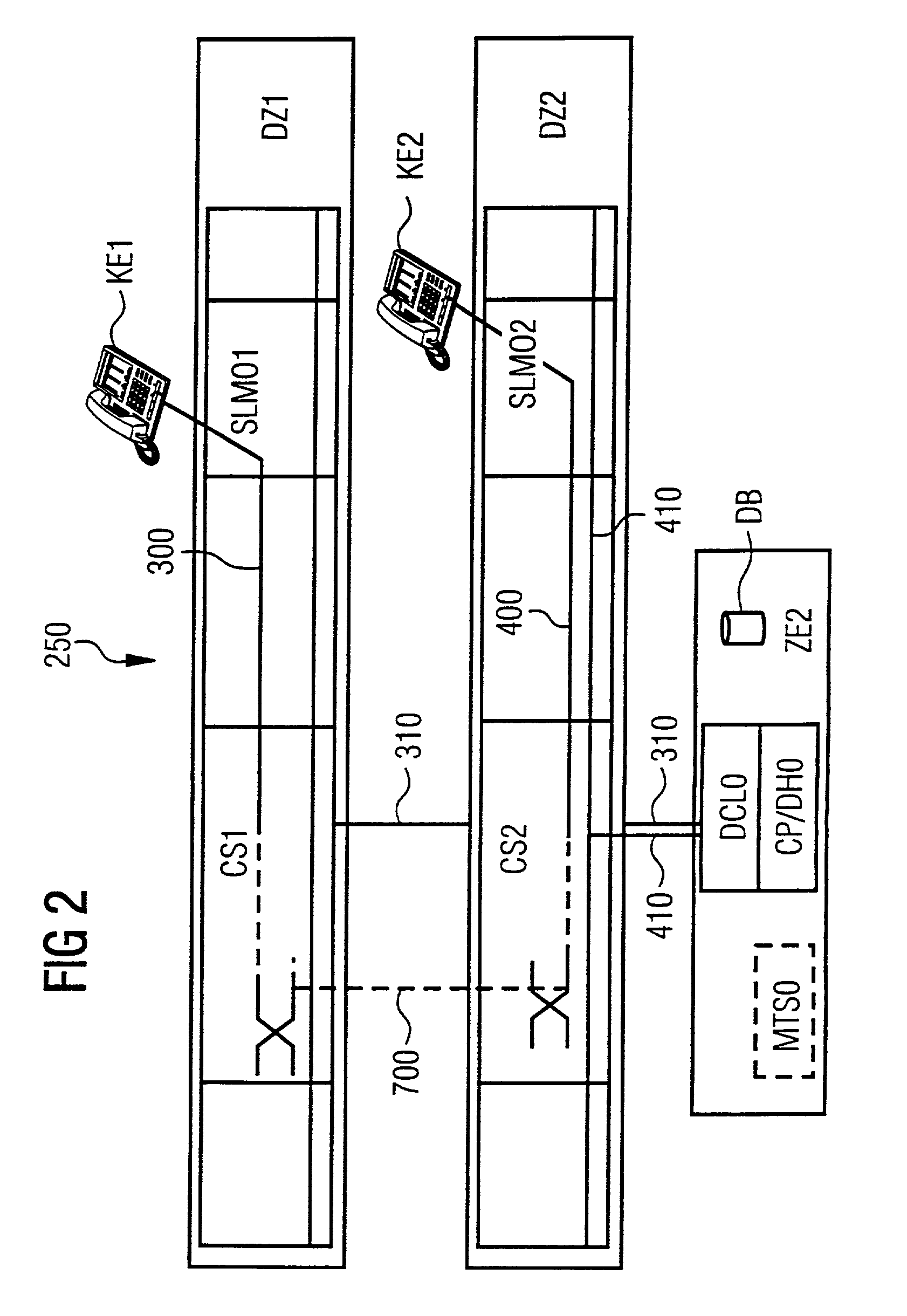
[0032]FIG. 2 shows an example of an arrangement for setting up, clearing down and operating communication connections via decentralized devices which are controlled by a central device. Here, for example, a private branch exchange 250 is represented. The same component parts of the device are denoted by the same reference numerals in FIG. 2 as in FIG. 1. It is notable in the case of this communication arrangement that there are a separate transport network 700 and an independent control network 310 / 410. Such a setup of an exchange has the advantage that already existing networks, in the form of public or private networks, can be used for the transport network. What is more, the control network has to be routed to the central device ZE2.

[0033]The digital or analog communication terminals KE1 and KE2 are represented in this representation in such a way that they are respectively connected to interface modules SLMO1 and SLMO2. Without restricting the invention, however, such terminals ...


PUM


Abstract

The invention describes a novel private branch exchange and the migration solution with respect to existing devices. Communication connections are established via a transport network, the control takes place in a centralized manner by means of a central control device, which is connected to the decentralized switching devices and the interface modules via a two-stage connection, a collection and distribution of the control messages being carried out in a decentralized manner and the control connection from the respective decentralized device to the central control being provided by an ATM network or an Ethernet connection.

Description

CLAIM FOR PRIORITY[0001]This application claims priority to International Application No. PCT / DE00 / 03175 which was published in the German language on Sep. 13, 2000.TECHNICAL FIELD OF THE INVENTION[0002]The invention relates to a method and an arrangement for transporting messages, and in particular, to control messages, in a switching device such as a private branch exchange set up over a large area, in which a number of decentralized devices are controlled from a central device.BACKGROUND OF THE INVENTION[0003]The requirements imposed on communication infrastructure installations, such as private branch exchanges for example, are constantly increasing. The cause for the increasing requirements with regard to the data transmission capacity of switching devices lies in the constantly increasing demand for voice, video and data communication and the consequence that networks of broader bands have to be used for establishing connections. The cause for greater flexibility with regard t...

Claims


Application Information

Patent Timeline
IPC IPC(8): H04J3/16H04L12/26H04L12/56H04Q3/545H04L12/24H04L12/70H04L29/06H04M3/00H04M3/42H04Q3/58H04Q3/62
CPCH04M3/42314H04M7/006H04Q3/625H04L2012/5618H04L2012/5665H04Q2213/13003H04Q2213/13031H04Q2213/13104H04Q2213/13204H04Q2213/1322H04Q2213/1329H04Q2213/13292H04Q2213/1334H04Q2213/13389
Inventor EMMERINK, ANTONIUSKLEIN, EGONSTEFFAN, ANDREASWINDECKER, RAINERWINKLER, STEFFI
Owner SIEMENS AG
Why Eureka
Try Eureka