Image forming apparatus with mode having prolonged rotation time of image bearing member at non-image forming time

a technology of image bearing member and rotation time, which is applied in the direction of electrographic process apparatus, corona discharge, instruments, etc., can solve the problems of image failure due to charging failure, prone to vary the charging potential of the surface of the photosensitive member to be charged accordingly, and complicated charging apparatus of the dc charging system, etc., to achieve high stability

Inactive Publication Date: 2006-12-26
CANON KK
View PDF14 Cites 0 Cited by
  • Summary
  • Abstract
  • Description
  • Claims
  • Application Information

AI Technical Summary

Benefits of technology

[0015]The present invention has been made in view of the above, and has an object to provide an image forming apparatus that performs charging with high stability through application of a voltage containing an AC component to a charging member.
[0016]Another object of the present invention is to provide an image forming apparatus that avoids cleaning failure or contamination of a charging member, which arises from vibration of a surface of an image bearing member due to an AC component applied to the charging member.
[0017]Another object of the present invention is to provide an image forming apparatus in which productivity of image forming is kept from being lowered as reliably as possible.
[0018]Still another object of the present invention is to provide an image forming apparatus in which it is made possible that a rotation time of an image bearing member is prolonged to remove a residual developer.
[0019]Still another object of the present invention is to provide an image forming apparatus in which selection can be made as to whether a time for promoting cleaning is provided or not.

Problems solved by technology

Under the comparison between the DC charging system and the AC charging system in the contact charging apparatus, the DC charging system has a disadvantage that, when a resistance value of the charging member varies due to an environmental change on a temperature, moisture, or the like, a charging potential of a surface of the photosensitive member to be charged is prone to vary accordingly.
Therefore, in the case of using the DC charging system, since it has been essential that the temperature or moisture in the environment where the charging apparatus is placed is always detected, and a voltage or current to be applied to the charging member is controlled based on the detected information, there has been a problem in that the DC charging system charging apparatus becomes complicated by being equipped with a temperature sensor or moisture sensor.
Further, in comparison to the AC charging system, the DC charging system presents a problem in that image failure due to charging failure is prone to develop even in the case where slight contamination of the charging member is generated by a lubricant between a cleaning member and an image bearing member or a waste developer that has passed through the cleaning member due to cleaning failure.
However, it is known that, when AC charging is used, an abrasion amount of a thickness of a surface layer of the image bearing member is increased compared with the case of using DC charging.
However, on the contrary, in the AC charging system, the surface of the image bearing member, which serves as a member to be cleaned, vibrates due to the applied AC component, chattering of the cleaning member develops, and thus, a transfer residual developer becomes difficult to be removed by cleaning means, which may lead to a case where cleaning property of the image bearing member is not sufficiently obtained.
In particular, when a spherical developer is used, there may be a case where a collecting property of the cleaning member is not sufficiently obtained.
Therefore, there still remains a problem in that, in the case where a non-image region does not exist between images in continuous printing, and thus, high-printing images are continuously output or in the case where a non-image region does not exist between images in continuous printing, and thus, high-printing images are continuously output in a multi-color or color image forming apparatus that uses an intermediate transferring member, a large amount of secondary transfer residual developer, which is inversely transferred from the intermediate transferring member to the image bearing member, cannot be fully cleaned by the cleaning member, which leads to the occurrence of image failure.

Method used


Image

  • Image forming apparatus with mode having prolonged rotation time of image bearing member at non-image forming time
  • Image forming apparatus with mode having prolonged rotation time of image bearing member at non-image forming time
  • Image forming apparatus with mode having prolonged rotation time of image bearing member at non-image forming time

Examples


embodiment 1

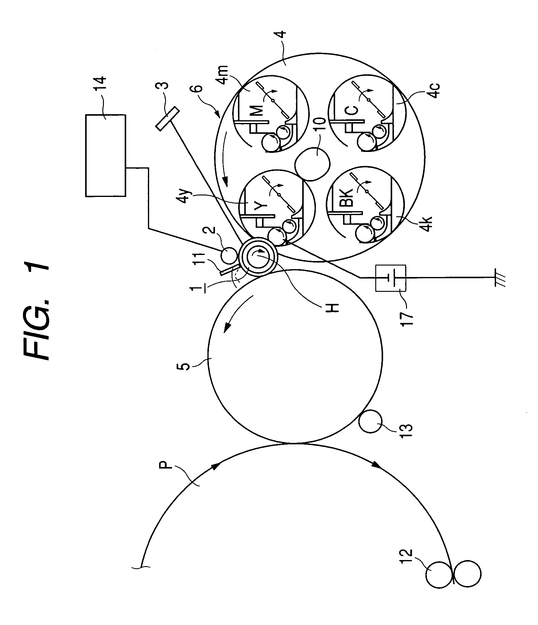
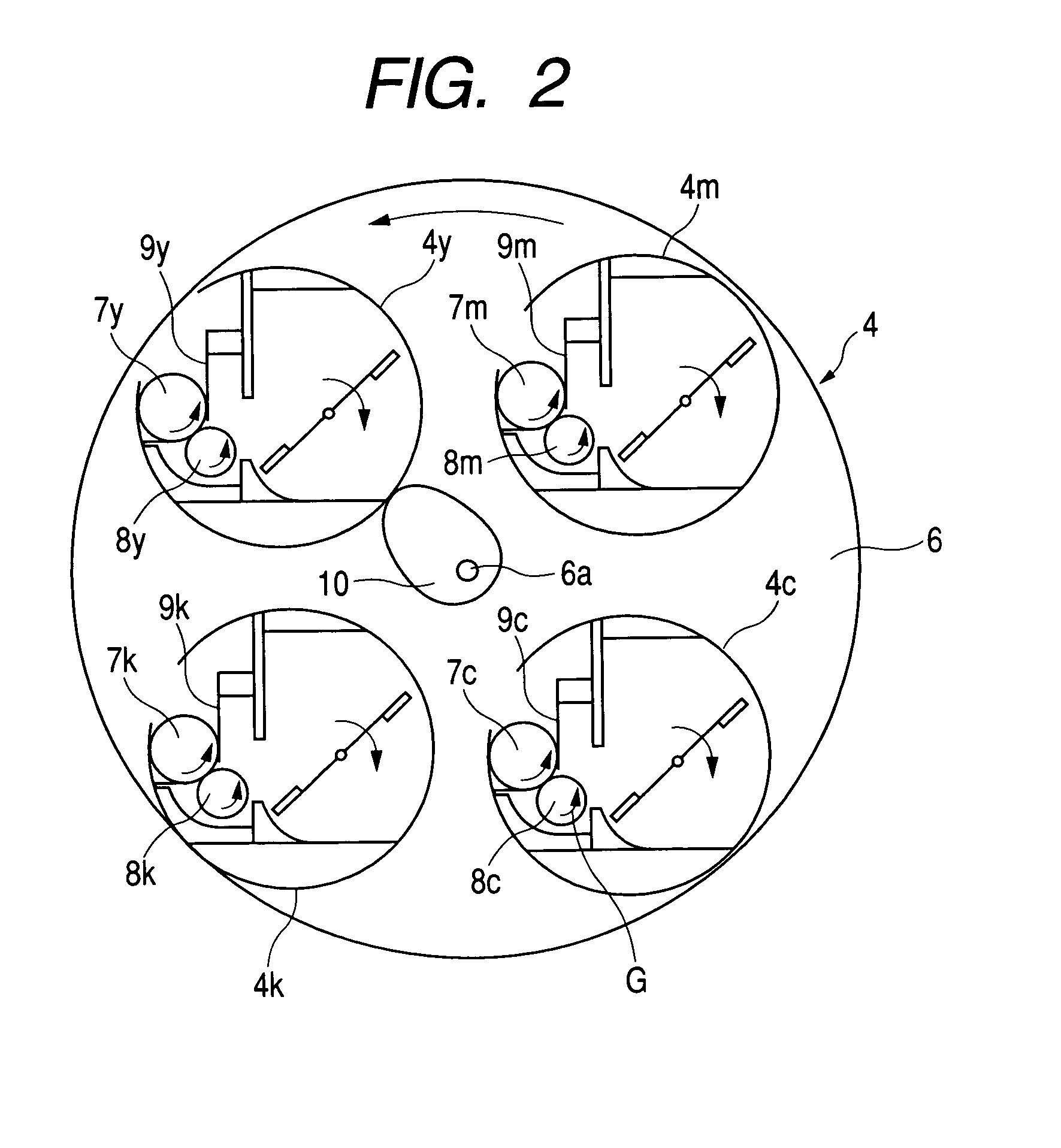
[0030]FIG. 1 is a schematic diagram of a multi-color image forming apparatus, such as a color laser printer, which corresponds to Embodiment 1 of the present invention.

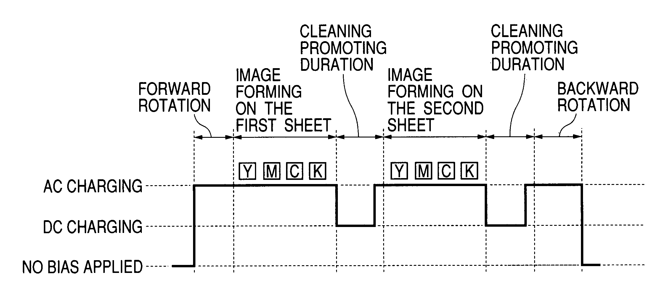
[0031]The multi-color image forming apparatus of this embodiment is characterized by including control means for performing switching to the mode in which the rotation time of an image bearing member is prolonged at the time of non-image forming, and an applied bias to a charging member is switched from a bias in which an AC component and a DC component are superimposed with each other to a bias only containing a DC component, that is, the mode in which cleaning of the image bearing member, which is different from a normal image forming operation, is promoted.

[0032]The multi-color image forming apparatus of this embodiment which is shown in FIG. 1 is mainly constituted by a photosensitive drum 1 serving as an image bearing member, a charging roller 2 that is a contact charging member 2 as a charger (charging device) w...

embodiment 2

[0056]FIG. 4 is a schematic diagram of a multi-color image forming apparatus, such as a laser printer, which corresponds to Embodiment 2 of the present invention.

[0057]The multi-color image forming apparatus in FIG. 4 is obtained by adding the control means 14, print rate detecting means 15, and environment detecting means 16 to the image forming apparatus in FIG. 1 which has been used for the explanation of the image forming apparatus in Embodiment 1.

[0058]While the user makes arbitrary selection on whether the cleaning promoting sequence is performed or not in Embodiment 1, this embodiment is characterized in that: the control means 14 makes judgment on whether the cleaning promoting sequence is required or not based on the detection results of the print rate detecting means 15 and the environment detecting means 16; and the control is automatically conducted. Here, the cleaning promoting sequence has the same contents as those in FIGS. 3A and 3B used for the explanation in Embodi...


PUM


Abstract

The image forming apparatus includes a rotatable image bearing member, a charging member that is contactably provided to the image bearing member and that charges the image bearing member with a voltage containing an AC component and a DC component; and a control device that makes selection on whether a mode, in which a rotation time of the image bearing member is prolonged and in which a voltage is applied to the charging member in the prolonged rotation time, is performed or not. As a result, the image forming apparatus is provided which performs charging with high stability.

Description

BACKGROUND OF THE INVENTION[0001]1. Field of the Invention[0002]The present invention relates to an image forming apparatus, which includes a charging member that is provided contactably to an image bearing member and charges the image bearing member, such as a laser printer, a copying machine, or a facsimile.[0003]2. Related Background Art[0004]Conventionally, an image forming apparatus, which uses an electrophotographic process or the like, such as a printer, a copying machine, or a facsimile is provided with a charging apparatus that charges a surface of an image bearing member.[0005]Examples of such charging apparatuses include a charging apparatus of corona discharging system and a charging apparatus of contact charging system which charges a surface of a photosensitive member through application of a voltage to a charging member in a state in which the charging member such as a charging roller is in direct contact with the photosensitive member.[0006]Further, the above-mention...

Claims


Application Information

Patent Timeline
Patent Type & Authority Patents(United States)
IPC IPC(8): G03G15/02G03G15/08G03G15/16G03G21/00G03G21/10
CPCG03G21/00G03G2215/021G03G2221/0005
Inventor NOGUCHI, BUNROTSUKIDA, SHINICHISUZUKI, JUN
Owner CANON KK
Why Eureka
Try Eureka