
Device for percutaneous nerve stimulation

a technology of percutaneous nerve stimulation and electrodes, applied in the field of electrical therapy, can solve the problems of affecting the accuracy of treatment, affecting the treatment effect, and affecting the patient's comfort, so as to eliminate the development of elastic force and not bend excessively

Inactive Publication Date: 2006-12-26
GAVRONSKY STAS
View PDF5 Cites 27 Cited by
  • Summary
  • Abstract
  • Description
  • Claims
  • Application Information

AI Technical Summary

Benefits of technology

[0013]It is an object of the invention to provide a device for percutaneous nerve stimulation that allows positioning and securing of the non-inserted part of the needle / electrode at an acute angle with the patient's skin and along the same axis with the inserted portion of the needle / electrode, so that the needle does not bend excessively at the skin surface, while staying close to it. A further object is to provide the aforementioned device of the type that allows change in a position of the inserted electrode in the body without compromising needle's sterility or without removing the whole electrical assembly. It is another object to provide a device for percutaneous nerve stimulation without contact of the needle with the patient's skin at an inclined position of the needle to the patient's skin. It is still another object to eliminate development of an elastic force in the needle during the use. It is a further object to provide the aforementioned device that allows a patient to have freedom of movements during percutaneous electrical nerve stimulation procedure without a risk of loosening the needle in the patient's skin or extracting the needle during patient's movements.
[0014]The present invention provides a novel device for portable percutaneous electrical nerve stimulation and electro-acupuncture. Unlike the existing device for portable percutaneous electrical nerve stimulation by the same applicant where an external part of the needle / electrode is kept in flush with the patient's skin after the needle is inserted at an acute angle, in this new device, the external part of the electrode is aligned with the rest of the needle and stays at an acute angle to the skin after the insertion. This eliminates a bent in the body of an electrode / needle at the point of its insertion into the skin and a consequent development of an elastic force that tends to straighten out the deformed needle. In the preferred embodiment, the device consists of a needle / electrode holder that has an electrode / needle guide channel and a power supply channel that intersects with the needle / electrode guide channel and serves for insertion of a pin electrode from an electrical generator (PENS unit). The pin electrode will provide an electrical contact with needle and at the same time function as means for securing the needle in a desire position in the guide channel.

Problems solved by technology

However, experience showed that patients experience some discomfort.
Furthermore, the known device exhibits some difficulty in use and precision control of the procedure because it is impossible to change a position of the inserted electrode in the body without compromising needle's sterility or without removing the whole electrical assembly.
This may loosen the part of the needle inserted into the skin and even lead to extraction of the needle from the skin because of friction contact of the needle handle with the patient's clothes.

Method used


Image

  • Device for percutaneous nerve stimulation
  • Device for percutaneous nerve stimulation
  • Device for percutaneous nerve stimulation

Examples


Embodiment Construction

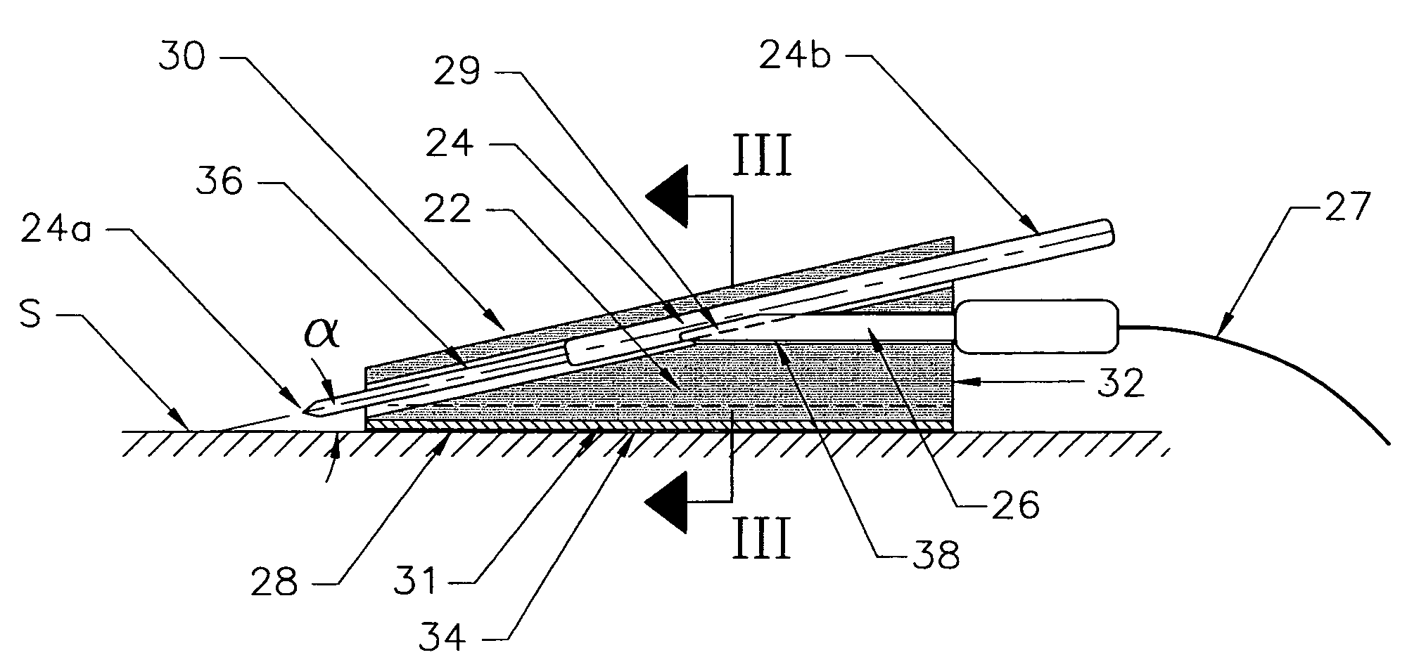
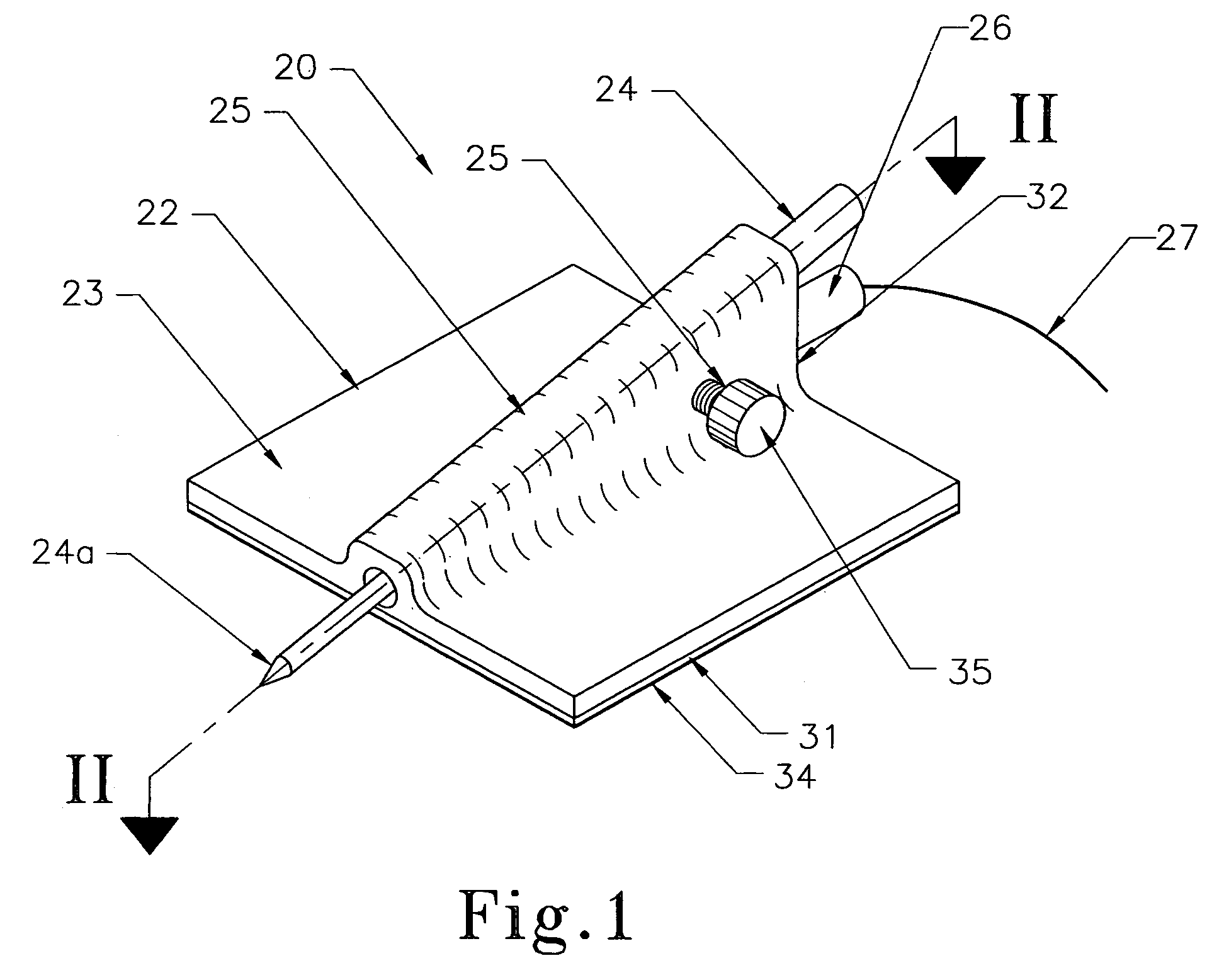
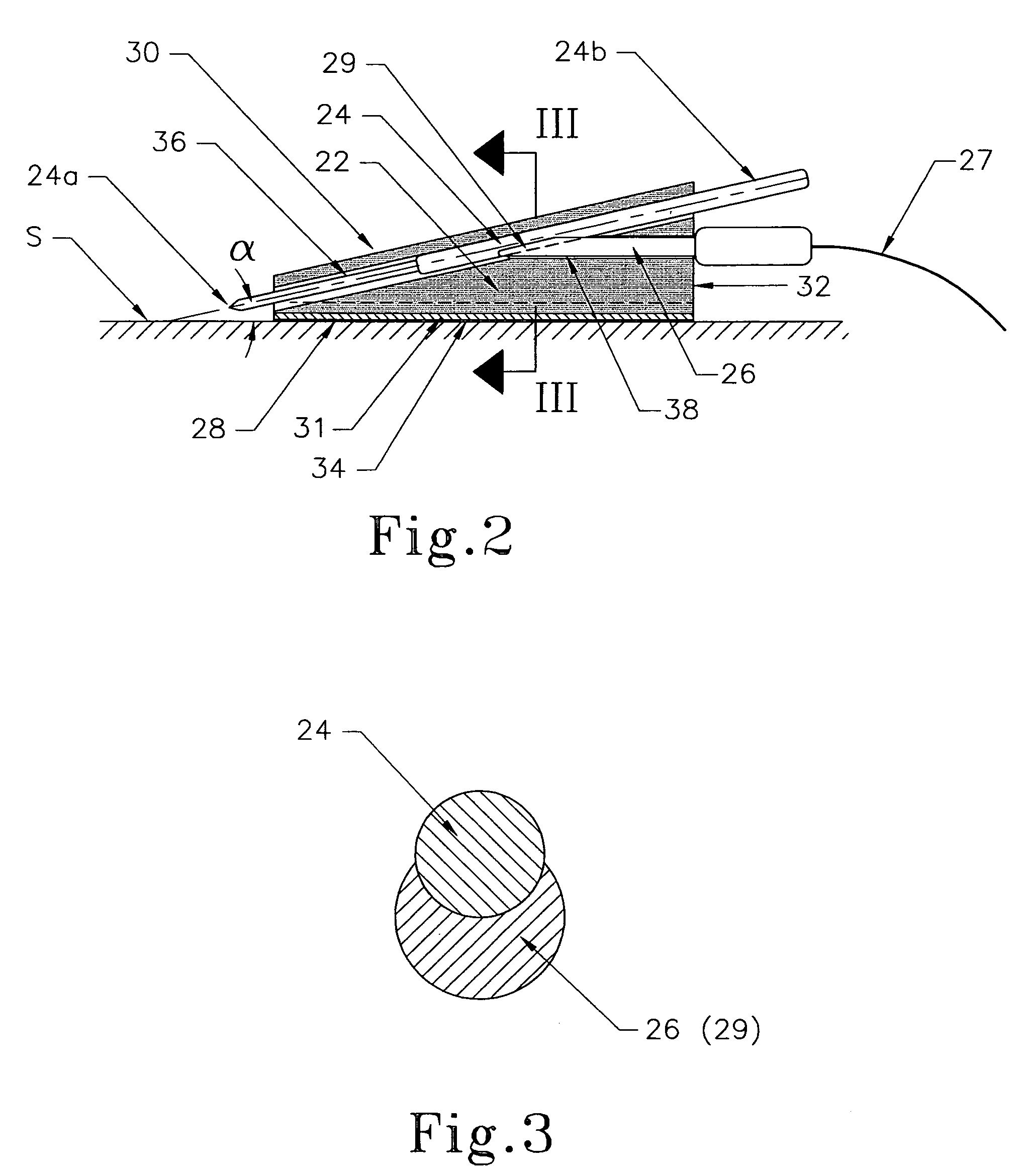
[0024]A device 20 for percutaneous nerve stimulation according to one embodiment of the invention is shown in FIG. 1, which is a three-dimensional view. FIG. 2 is a sectional view of the device along the line II—II. The device 20 is comprised of a needle / electrode holder 22, a needle / electrode 24, and a terminal pin 26 for supply of power to the needle / electrode 24.

[0025]As can be seen from FIGS. 1 and 2, the needle / electrode holder 22 is comprised of a plate-like base 23 with a ridge 25 in the middle of the base 23. The ridge extends in the direction coaxial with the direction of insertion of the needle / electrode. The needle / electrode holder 22 has a triangular cross section in the direction of line II—II shown in FIG. 1. It has a flat bottom side 28 (the side of the triangle opposite to the hypotenuses), an inclined upper side 30 of the ridge 25 (the hypotenuses of the triangle), and a second non-hypotenuses side 32 of the ridge, the direction of which is not critical. The needle ...


PUM


Abstract

The present invention provides a novel device for portable percutaneous electrical nerve stimulation and electro-acupuncture. In the preferred embodiment, the device consists of a needle / electrode holder that has a linear electrode / needle guide channel and a power supply channel that intersects with the needle / electrode guide channel and serves for insertion of a pin electrode from an electrical generator (PENS unit). The pin electrode will provide an electrical contact with the needle and at the same time function as means for securing the needle in a desire position in the guide channel. The needle remains straight and the extended portion thereof is kept out of contact with the patient's skin.

Description

CROSS-REFERENCE TO RELATED APPLICATIONS[0001]The present patent application is related to pending U.S. patent application Ser. No. 10 / 962,299 filed by the same applicant on Oct. 9, 2004BACKGROUND OF THE INVENTION[0002]1. Field of the Invention[0003]The present invention relates to the field of electrical therapy for treating pain and other conditions, in particular to electro-acupuncture and percutaneous electrical nerve stimulation therapy. The present invention is more specifically directed to a method and device capable of delivering continuous pain relief through percutaneous electrical nerve stimulation both in and out of clinic.[0004]2. Prior Art[0005]Electrical therapy has long been used in medicine to treat pain and other conditions. One of the forms of electrical therapy is Transcutaneous Electrical Nerve Stimulation (TENS). The TENS method is based on a hypothesis of Melzack and Wall from 1965. They proposed that activity in coarse, afferent nerve fibers (A-beta-fibers tha...

Claims


Application Information

Patent Timeline
Patent Type & Authority Patents(United States)
IPC IPC(8): A61N1/04
CPCA61H39/002A61H39/08A61N1/0502A61N1/36021A61N1/36017Y10S128/907
Inventor GAVRONSKY, STAS
Owner GAVRONSKY STAS
Learn More