
Prefabricated housing structure

a housing structure and prefabricated technology, applied in the field of prefabricated housing structures, can solve the problems of additional shipping costs and the need for two or more workers, and achieve the effect of convenient assembly and disassembly

Active Publication Date: 2007-01-02
CERTIFIED LUMBER
View PDF14 Cites 31 Cited by
  • Summary
  • Abstract
  • Description
  • Claims
  • Application Information

AI Technical Summary

Benefits of technology

Enables easy and efficient assembly and disassembly of lightweight, cost-effective housing structures that can be easily stored and erected by a single person, reducing shipping costs and labor requirements.

Problems solved by technology

However, the use of relatively large panels results in additional shipping cost and relatively heavy panels which results in the need for two or more workers to accomplish the erection process.

Method used


Image

  • Prefabricated housing structure
  • Prefabricated housing structure
  • Prefabricated housing structure

Examples


Embodiment Construction

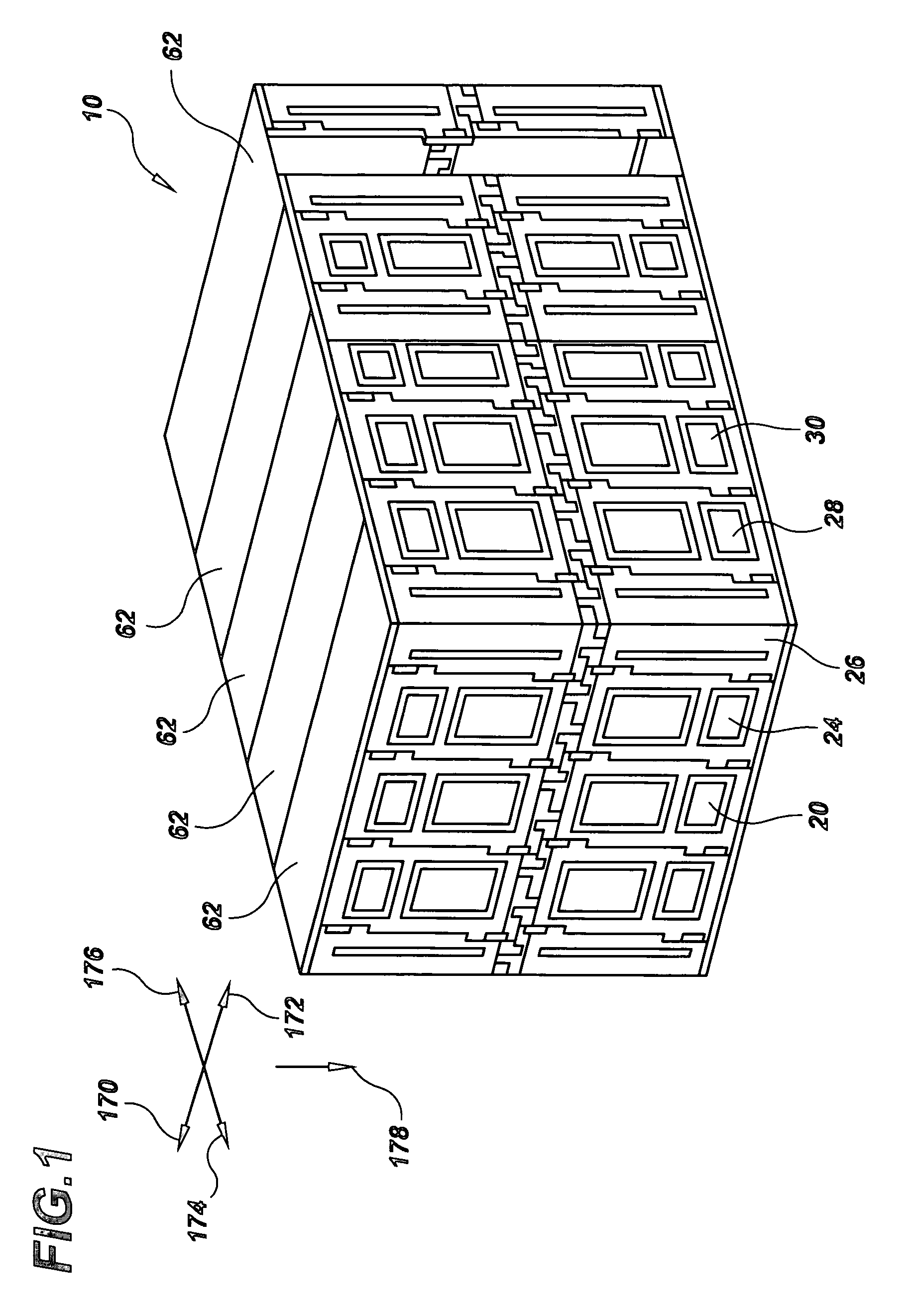
[0039]With reference to the drawings, there is shown in FIG. 1 a prefabricated housing structure 10 made in accordance with the present invention.

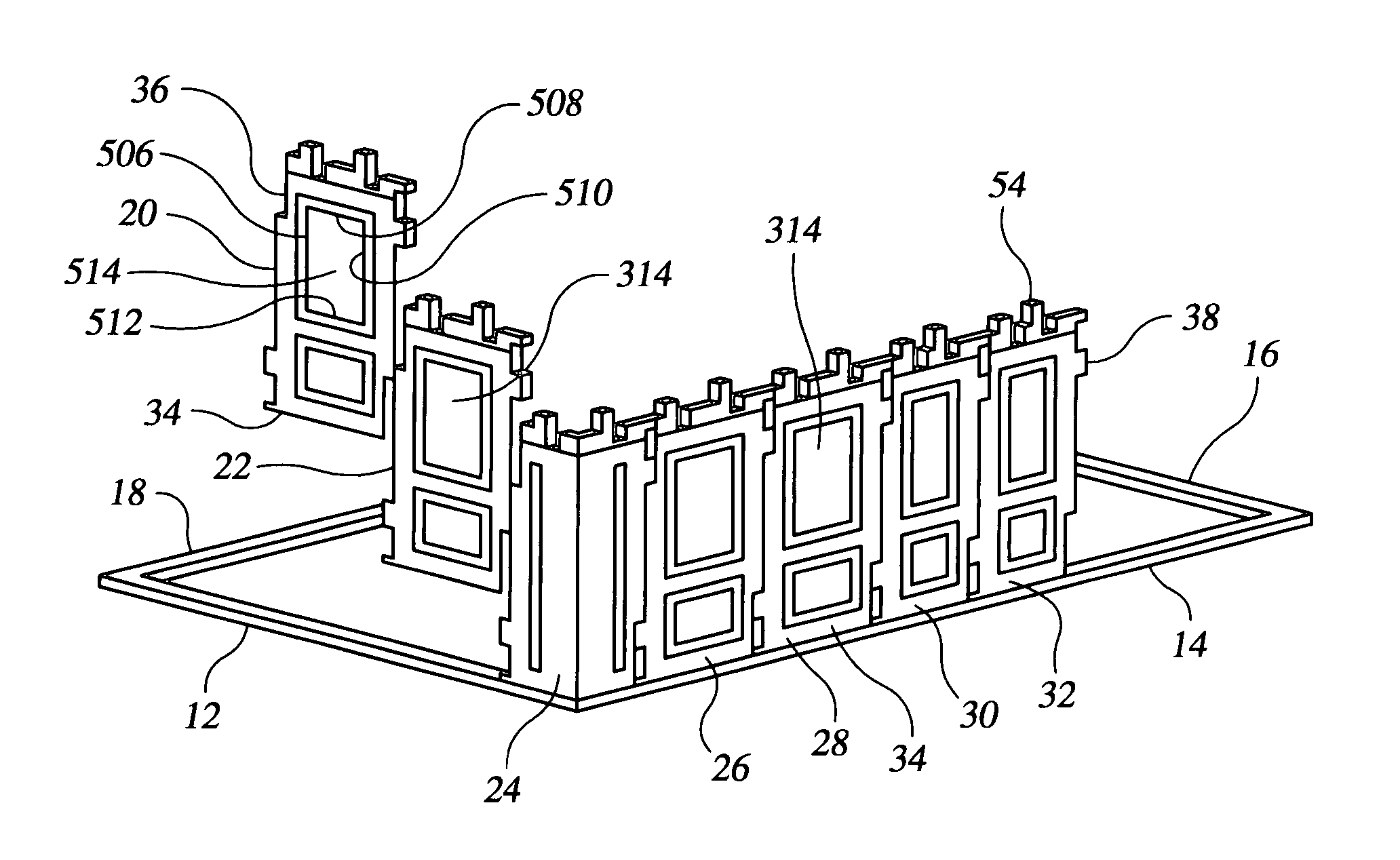
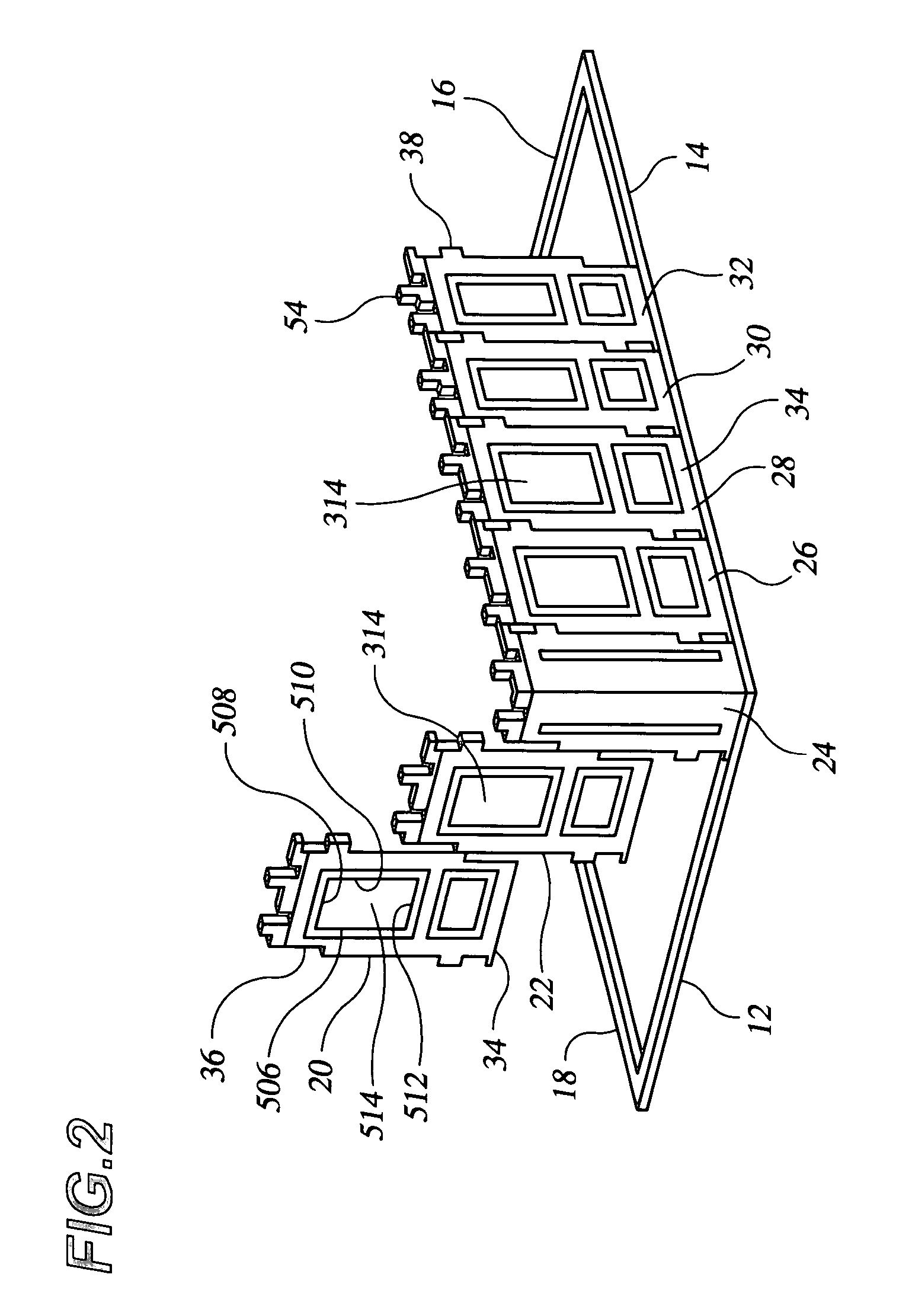
[0040]FIG. 2 shows the first two steps in the erection of the prefabricated housing structure 10 showing the placement of the base channels 12, 14, 16, 18. The first step comprises the placement of the base channels 12, 14, 16, 18 to form a rectangle which defines the perimeter of the structure.

[0041]The second step includes the placement of the lower panels 20, 22, 26, 28, 30, 32. The lower panels 20, 22, 26, 28, 30, 32 are shown with their bottom portions 34 inserted into the base channels 12, 14, 16, 18. FIG. 2 also shows the corner panel 24 and the method of interlocking the individual lower panels to form the first course 54 of walls 36, 38.

[0042]FIG. 3 shows the third step which includes the placement of the upper panels 40, 42, 44, 46, 48, 50, 52 to form the second course 56 of the walls 36, 38. As shown in FIG. 3, the lower edges 5...


PUM


Abstract

A housing structure includes a first plurality of wall panels which form a lower course and a second plurality of wall panels which form an upper course. Each of the wall portions is generally rectangular and includes integrally formed interlocking portions which facilitate attachment of adjacent lateral edges of the wall portions of the first plurality to each other. Integrally formed interlocking portions facilitate attachment of the panels in the lower course to the panels in the upper course. In addition, rectangular roof panels are provided to enclose the housing structure. The interlocking portions enable the panels to slide into an interlocked engagement configuration thereby forming a rigid structure without the need for tools.

Description

RELATED APPLICATIONS[0001]This application claims priority from Provisional Application No. 60 / 501,694, filed Sep. 9, 2003, and Provisional Application No. 60 / 500,089, filed Sep. 4, 2003.FIELD OF THE INVENTION[0002]The present invention relates generally to the field of housing structures and more particularly to a prefabricated housing structure having a plurality of interlocking panels.BACKGROUND OF THE INVENTION[0003]The prior art related to housing structures includes numerous examples of prefabricated structures. These structures are typically composed of a plurality of prefabricated flat panels which are assembled at the location of use to form a structure. The assembly of conventional prefabricated operation generally involves the use of various fasteners which require various hand or power tools. The fasteners are used to join the edges of the panels to form rigid structure. In an effort to overcome the disadvantages associated with the need to assemble the relatively large ...

Claims


Application Information

Patent Timeline
Patent Type & Authority Patents(United States)
IPC IPC(8): E04H1/00E04B1/12E04B1/61E05D15/06
CPCE04B1/12E05D15/0647E04B1/6179Y10T403/7094Y10T403/7092F16B2200/30
Inventor ROSENBERG, ABRAHAM
Owner CERTIFIED LUMBER
Learn More