Dual diameter and rotating centralizer/sub

a centralizer/sub and rotating technology, applied in the field of centralizers, can solve the problems of not having a centralizer capable, no centralizer is known that provides effective centralization in both bores, and the tendency of rotation to damage the bow springs of such centralizers, so as to reduce the diameter of the centralizer, reduce the diameter, and limit the longitudinal movement of the collar

Inactive Publication Date: 2007-01-02
TERCEL OILFIELD PROD USA L L C
View PDF85 Cites 17 Cited by
  • Summary
  • Abstract
  • Description
  • Claims
  • Application Information

AI Technical Summary

Benefits of technology

[0012]These objects are achieved by providing a centralizer adapted for concentric mounting on a sub, the sub having a shoulder formed on the outside diameter thereof, comprising a collar having a groove formed in the inside surface thereof adapted for receiving the shoulder formed on the outside diameter of the sub therein when concentrically mounted on the sub to limit longitudinal movement of the collar along the sub. The collar may also be provided with a portion of reduced outside diameter to which a plurality of bow springs are mounted, the bow springs being maintained in spaced relation to the sub whereby one or more of the bow springs moves between a first, bowed position standing off from the body to a second compressed position closer to the body. In one preferred embodiment, the ends of the bow springs are mounted to the reduced diameter portion of the collar in notches formed in the reduced diameter portion of the collar, thereby reducing the diameter of the centralizer enough that movement of the centralizer through reduced diameter portions of the borehole and / or wellhead equipment is facilitated.

Problems solved by technology

However, there are at least two disadvantages of prior known centralizers in that they tend to restrict fluid flow in the annular space between centralizer O.D. and the I.D. of the tubular member and, in the event the smaller diameter tubular member needs to be rotated inside the larger diameter tubular member (if, for instance, it becomes stuck during running), rotating tends to damage the bow springs of such centralizers.
Another disadvantage of many known centralizers is illustrated by reference to the many wells that include a portion that is cased and a portion that is not cased, wells in which the diameter of the bore changes, or wells that include one or more lateral bores.
So far as is known, no centralizer is available that is capable of both being run into such bores and then also providing effective centralizing in a larger diameter portion of the wellbore.
Similarly, no centralizer is known that provides effective centralizing in bores of both diameters.
Another limitation of known centralizers occurs in the curved portion of a wellbore.
This same problem of the weight of the tubing affects lateral bores, restricting fluid flow and preventing the rotation of the tubing string.
Another limitation of known centralizers occurs when the wellbore, or a portion of the wellbore, wellhead, or flow control equipment is of relatively small diameter.
Further, because of the increased tendency of the bow springs to return to their uncompressed state as a result of their high compression, the likelihood that the centralizer will catch and hang up in the wellbore, wellhead, or flow control equipment is increased.
The high compression that is required in such restrictions in the wellbore is sometimes even enough to overcome the restoring force of the bow springs such that the bow springs are unable to return to their uncompressed state.

Method used


Image

  • Dual diameter and rotating centralizer/sub
  • Dual diameter and rotating centralizer/sub
  • Dual diameter and rotating centralizer/sub

Examples


Embodiment Construction

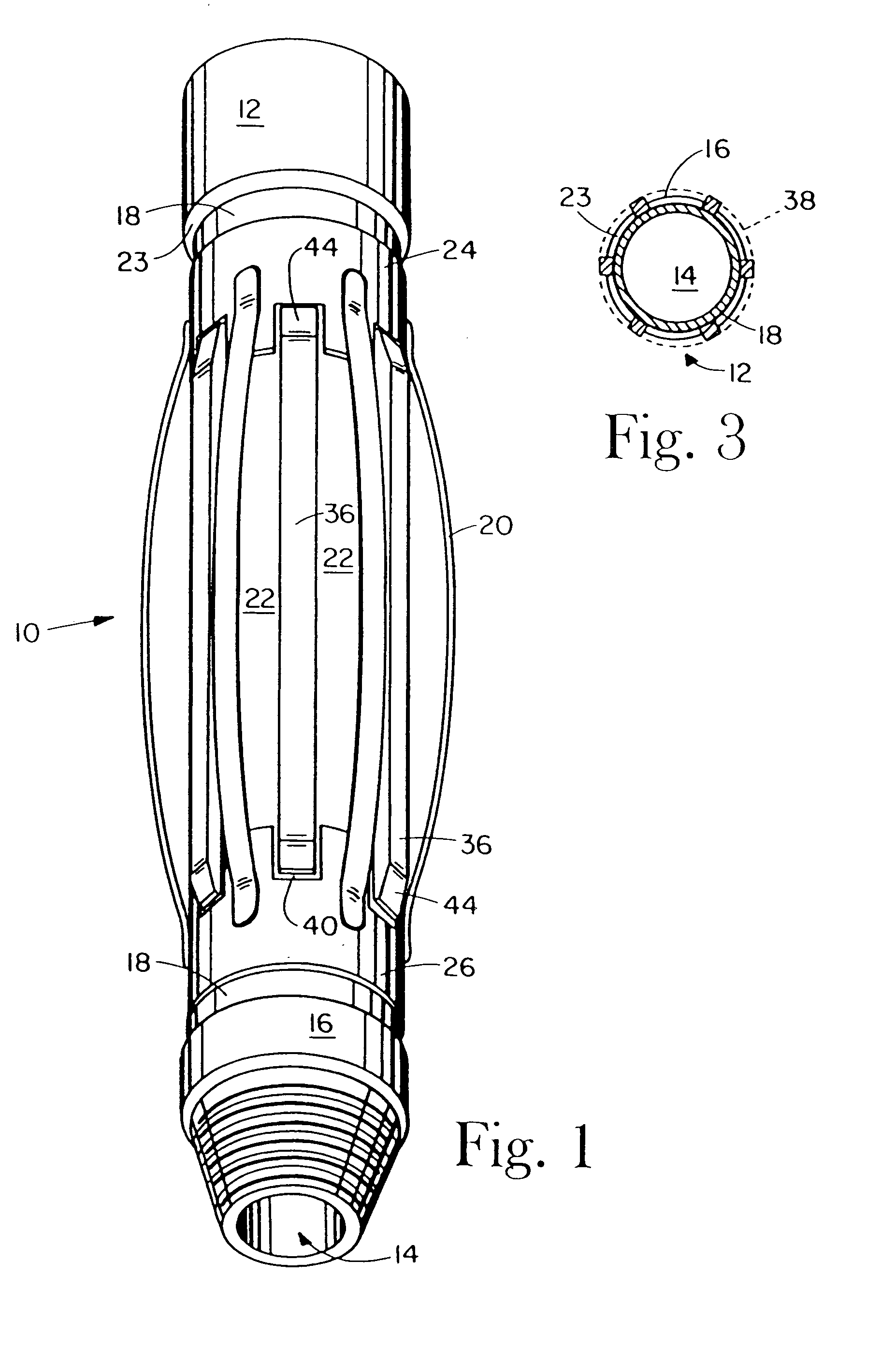
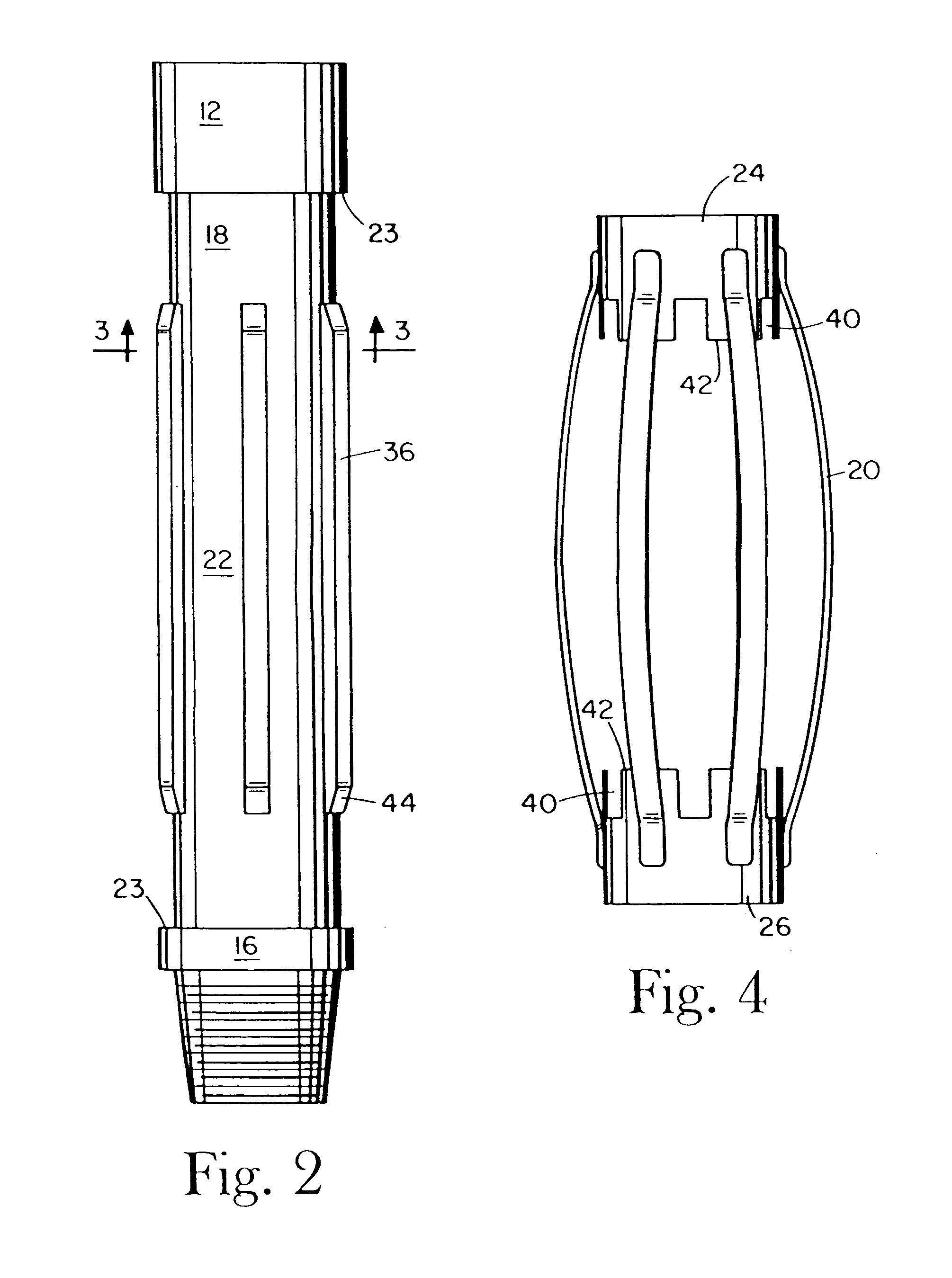
[0029]Referring to FIG. 1, a preferred embodiment of a centralizer constructed in accordance with the teachings of the present invention is indicated generally at reference numeral 10. In the embodiment shown, centralizer 10 is comprised of a tubular body 12 having a bore 14 therethrough and an outer surface, or O.D., 16. The O.D. 16 of body 12 is provided with a groove 18 in which the first and second collars 24, 26 are movably disposed, the ends 28 of a plurality of bow springs 20 being affixed to each of collars 24, 26 by, for instance, welding or other suitable means of attachment. Bow springs 20 are spaced apart around the collars 24, 26. Although not shown in the figures, those skilled in the art who have the benefit of this disclosure will recognize that one or both of collars 24, 26 move apart from each other when the bow springs are moved from the first, bowed position standing off from said body as shown in FIG. 1 to a second, compressed position closer to body 12 as centr...


PUM


Abstract

A centralizer for maintaining stand-off and/or centralizing a tubular member inside a larger diameter tubular member, for instance, in a wellbore. The centralizer is provided with bow springs that compress to a minimal diameter around the outer diameter of the sub to which the centralizer is concentrically mounted when compressive force is applied to the bow springs to facilitate insertion of the centralizer into restricted openings and/or flow control or wellhead equipment. The minimal diameter of the centralizer is provided by mounting the bow springs to a reduced diameter portion of the collar that is mounted to the sub, and even greater reduction in diameter is achieved by mounting the bow springs in notches formed in the reduced diameter portion of the collar.

Description

CROSS REFERENCE TO RELATED APPLICATION[0001]The present application is a continuation-in-part of co-pending application Ser. No. 10 / 302,641, DUAL DIAMETER AND ROTATING CENTRALIZER / SUB AND METHOD, filed Nov. 23, 2002. Ser. No. 10 / 302,641 is itself a continuation-in-part of application Ser. No. 09 / 655,795, filed Sep. 6, 2000, and having the same title, now issued as U.S. Pat. No. 6,484,803, and Applicant hereby claims the benefit of the earlier filing dates of both prior applications under 35 U.S.C. 120.BACKGROUND OF THE INVENTION[0002]The present invention relates to a centralizer for use in wellbore operations. More specifically, the present invention relates to a centralizer with compressible bow springs, particularly a stabilizer that is used in relatively small annular spaces and which also expands for use in a larger annular space. In another aspect, the present invention relates to a centralizer that provides a minimum standoff and / or centralization in portions of a wellbore in...

Claims


Application Information

Patent Timeline
Patent Type & Authority Patents(United States)
IPC IPC(8): E21B17/10
CPCE21B17/1078E21B17/1028
Inventor GREMILLION, MAXIMILLIAN S.
Owner TERCEL OILFIELD PROD USA L L C
Why Eureka
Try Eureka