Apparatus and system for welding preforms and associated method

a technology of apparatus and preforms, applied in the field of friction stir welding, can solve the problems of high cost and time consumption

Inactive Publication Date: 2007-01-02
THE BOEING CO
View PDF12 Cites 38 Cited by
  • Summary
  • Abstract
  • Description
  • Claims
  • Application Information

AI Technical Summary

Benefits of technology

[0008]The invention addresses the above needs and achieves other advantages by providing an assembly for positioning a structural assembly for friction stir welding preforms, as well as an associated system and method for friction stir welding preforms. The structural assembly is capable of being arranged in a variety of configurations to secure the structural members during friction stir welding, to create various preforms, and to promote efficient assembly before friction stir welding and disassembly after welding.
[0015]The present invention therefore provides an assembly that is capable of arranging structural members in a variety of configurations prior to friction stir welding. The assembly eliminates separate tooling for clamping each of the structural members prior to friction stir welding, which consequently reduces the cost of friction stir welding preforms. The spacers are capable of adequately securing the structural members during friction stir welding, and are shaped and sized to promote removal of the spacers following welding even when the structural members expand. Furthermore, the assembly is capable of positioning the structural members for fabricating a variety of preforms that may later be machined into a finished part.

Problems solved by technology

Both methods require that each structural member be separately clamped for welding, which is expensive and time consuming.

Method used


Image

  • Apparatus and system for welding preforms and associated method
  • Apparatus and system for welding preforms and associated method
  • Apparatus and system for welding preforms and associated method

Examples


Embodiment Construction

[0026]The present invention now will be described more fully hereinafter with reference to the accompanying drawings, in which some, but not all embodiments of the invention are shown. Indeed, this invention may be embodied in many different forms and should not be construed as limited to the embodiments set forth herein; rather, these embodiments are provided so that this disclosure will satisfy applicable legal requirements. Like numbers refer to like elements throughout.

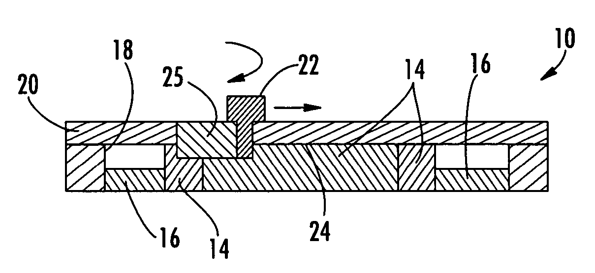
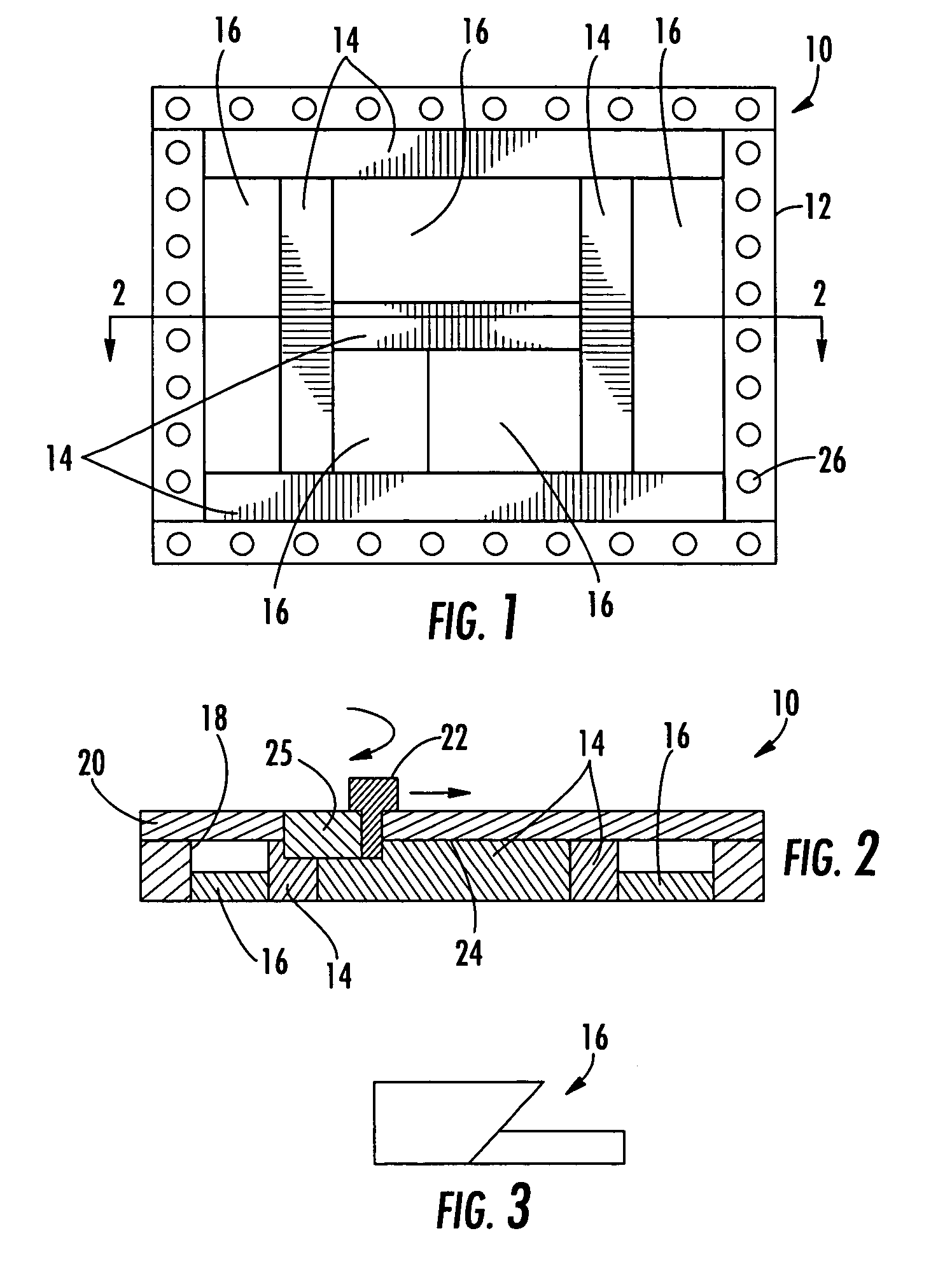
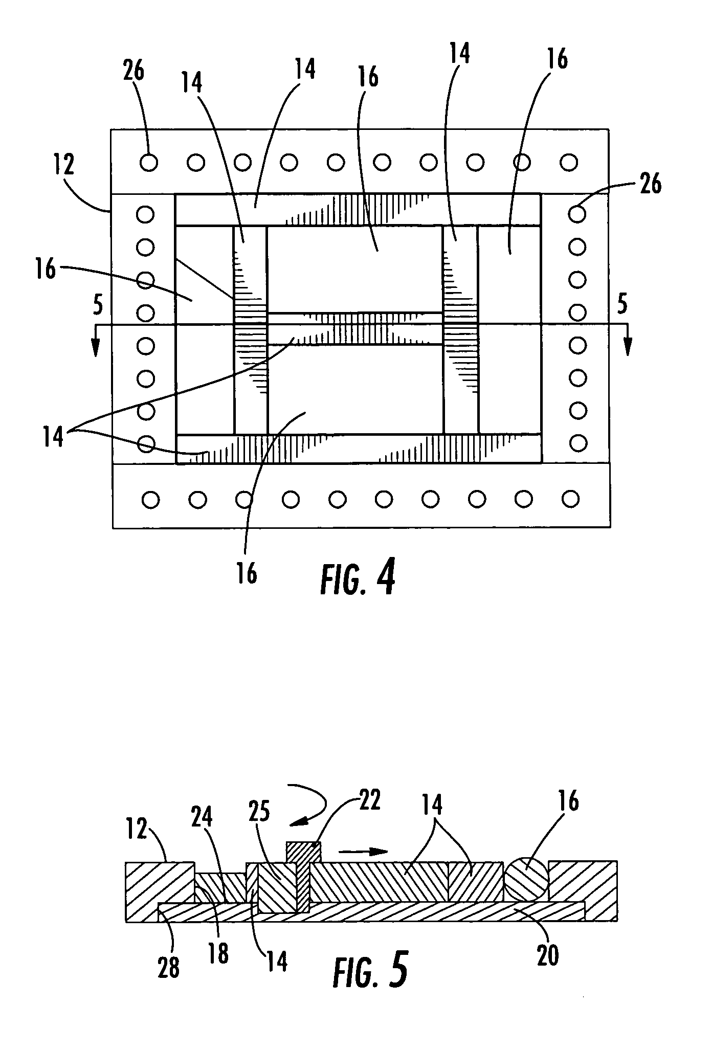
[0027]Referring now to the drawings and, in particular to FIGS. 1–2 there is shown a structural assembly 10 that is capable of being friction stir welded into a preform. The structural assembly 10 includes a frame 12 and a plurality of structural members 14 and spacers 16 arranged within an aperture 18 defined within the frame. A substrate 20 is positioned adjacent to the structural members 14, typically in an underlying or overlying relationship, such that a probe 22 can be used to friction stir weld the structur...


PUM

PropertyMeasurementUnit
angleaaaaaaaaaa
resistance forceaaaaaaaaaa
forceaaaaaaaaaa

Abstract

An assembly for positioning a structural assembly for friction stir welding, and a system and method for friction stir welding the structural assembly are provided. The assembly includes a frame defining an aperture therein, and at least one structural member positioned within the aperture. The assembly also includes at least one spacer positioned within the aperture such that the spacer and structural member substantially fill the aperture to secure the structural member within the frame, as well as a substrate secured to the frame and positioned adjacent to the structural member in an overlapping configuration to define an interface between the substrate and structural member. In this configuration, the substrate and structural member are capable of being friction stir welded together.

Description

BACKGROUND OF THE INVENTION[0001]1) Field of the Invention[0002]The present invention relates to friction stir welding and, more particularly, to positioning a structural assembly for friction stir welding and friction stir welding the structural assembly to form a preform.[0003]2) Description of Related Art[0004]Friction stir welding is a process in which a rotating tool, such as a pin or probe, is urged into and / or through a workpiece, e.g., to join multiple members of the workpiece in a solid state or to repair cracks in a workpiece. Typically, the pin extends from a shoulder, which can be flat, concave, or otherwise contoured, and the shoulder is urged against the workpiece so that the pin is urged therein. The pin is then urged through the workpiece to form a continuous weld joint. For example, during one conventional friction stir welding process, the probe of the rotating tool is plunged into a workpiece or between two workpieces by a friction stir welding machine to produce ...

Claims


Application Information

Patent Timeline
Patent Type & Authority Patents(United States)
IPC IPC(8): B23K31/02
CPCB23K20/126
Inventor SLATTERY, KEVIN T.
Owner THE BOEING CO
Why Eureka
Try Eureka