
Secure mounting system for overhead mounted projector

a projector and mounting system technology, applied in the field of visual projector mounting systems, can solve the problems of projector units being attractive targets for theft, vandalism and other tampering, and the space where the projector is installed may be unsecured, and achieve the effect of easy adjustment of positioning

Active Publication Date: 2007-01-02
LEGRAND AV INC
View PDF31 Cites 62 Cited by
  • Summary
  • Abstract
  • Description
  • Claims
  • Application Information

AI Technical Summary

Benefits of technology

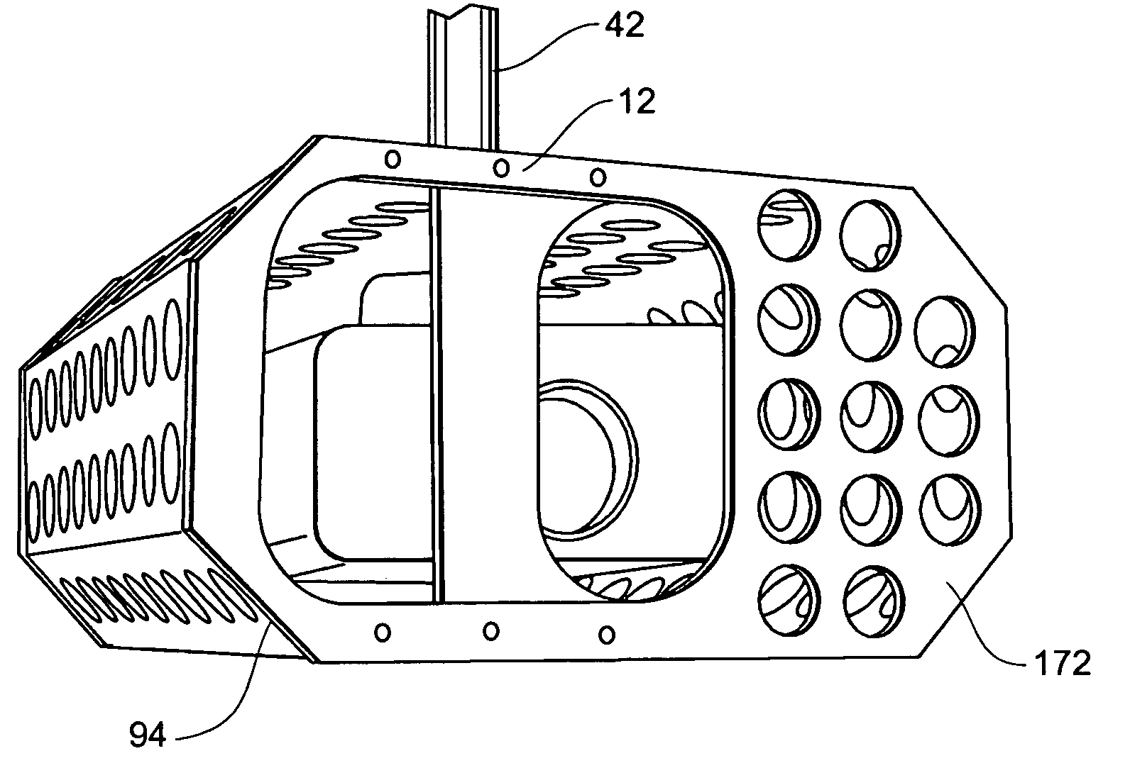
[0008]The present invention is an adjustable tamper-resistant overhead mounting system for a an LCD, CRT or DCP projector that addresses the aforementioned need in the industry. The adjustable mount bracket of the present invention includes brackets attachable to the projector and a suspension member attached to an overhead structure. At least one tamper resistant fastener is used at each connection of the brackets, the projector and the suspension member, to deter theft and tampering. The brackets enable inverted mounting of the projector from the ceiling structure of a space. The arrangement of the brackets may enable easy adjustable positioning of the projector about pitch, roll and yaw axes. The projector may also be enclosed in an enclosure system to protect against contact by foreign objects. The enclosure is adapted to be installable without removing the projector or otherwise disturbing the mounting system.

Problems solved by technology

Projectors, particularly LCD, CRT, and DRP projectors designed for frequent use in a setting such as described above are quite expensive.
In addition, the spaces where the projector is installed may be unsecured for periods of time or left unattended.
Consequently, a problem is that projector units are attractive targets for theft, vandalism and other tampering.
Another problem is that in some multi-use spaces, such as gymnasiums, the projector unit can be exposed to the possibility of unintentional or intentional contact by objects such as balls or other similar flying objects.

Method used


Image

  • Secure mounting system for overhead mounted projector
  • Secure mounting system for overhead mounted projector
  • Secure mounting system for overhead mounted projector

Examples


Embodiment Construction

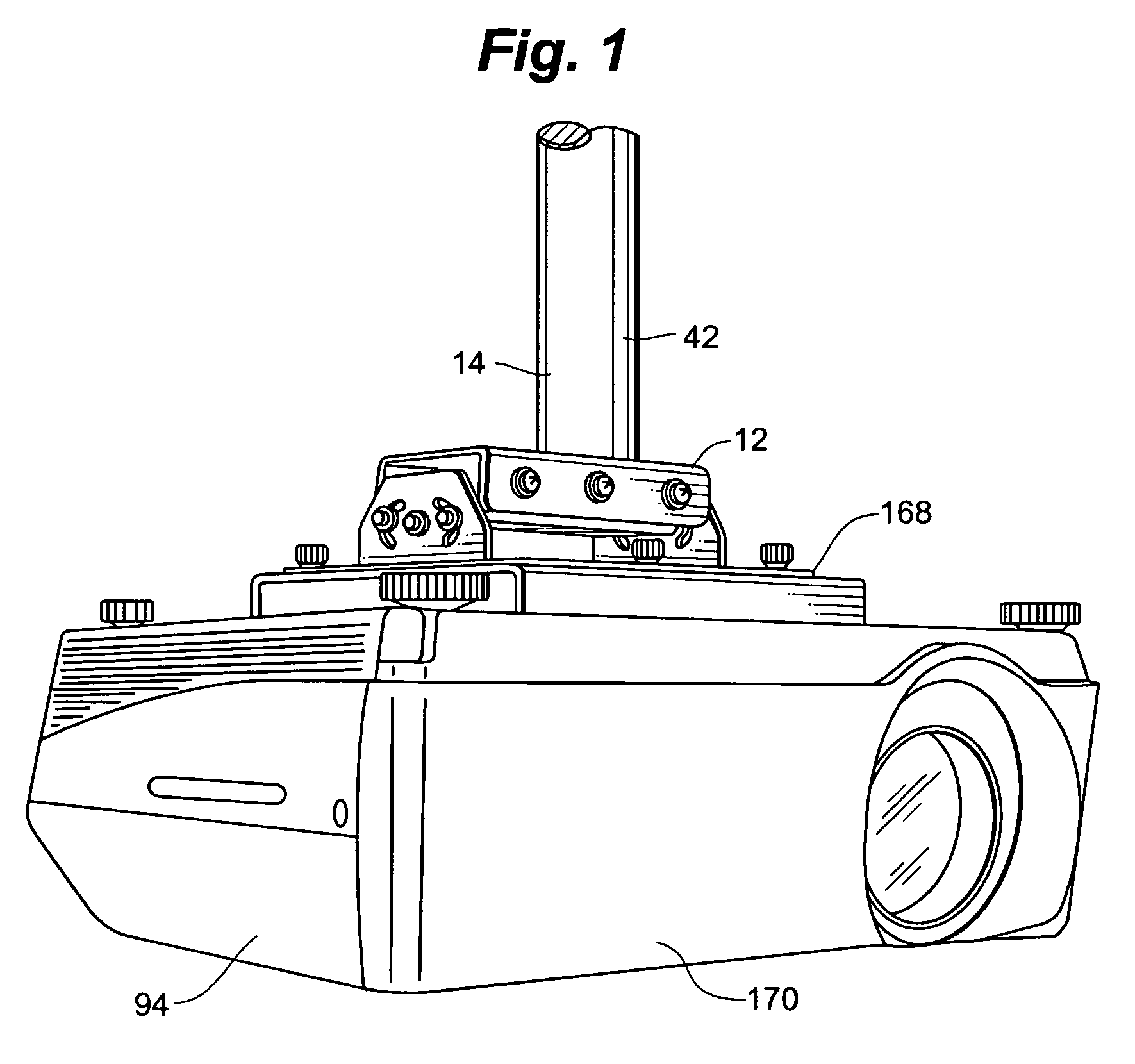
[0031]A tamper resistant visual projector mounting system 10 generally includes an adjustable bracket 12 and a suspension member 14.

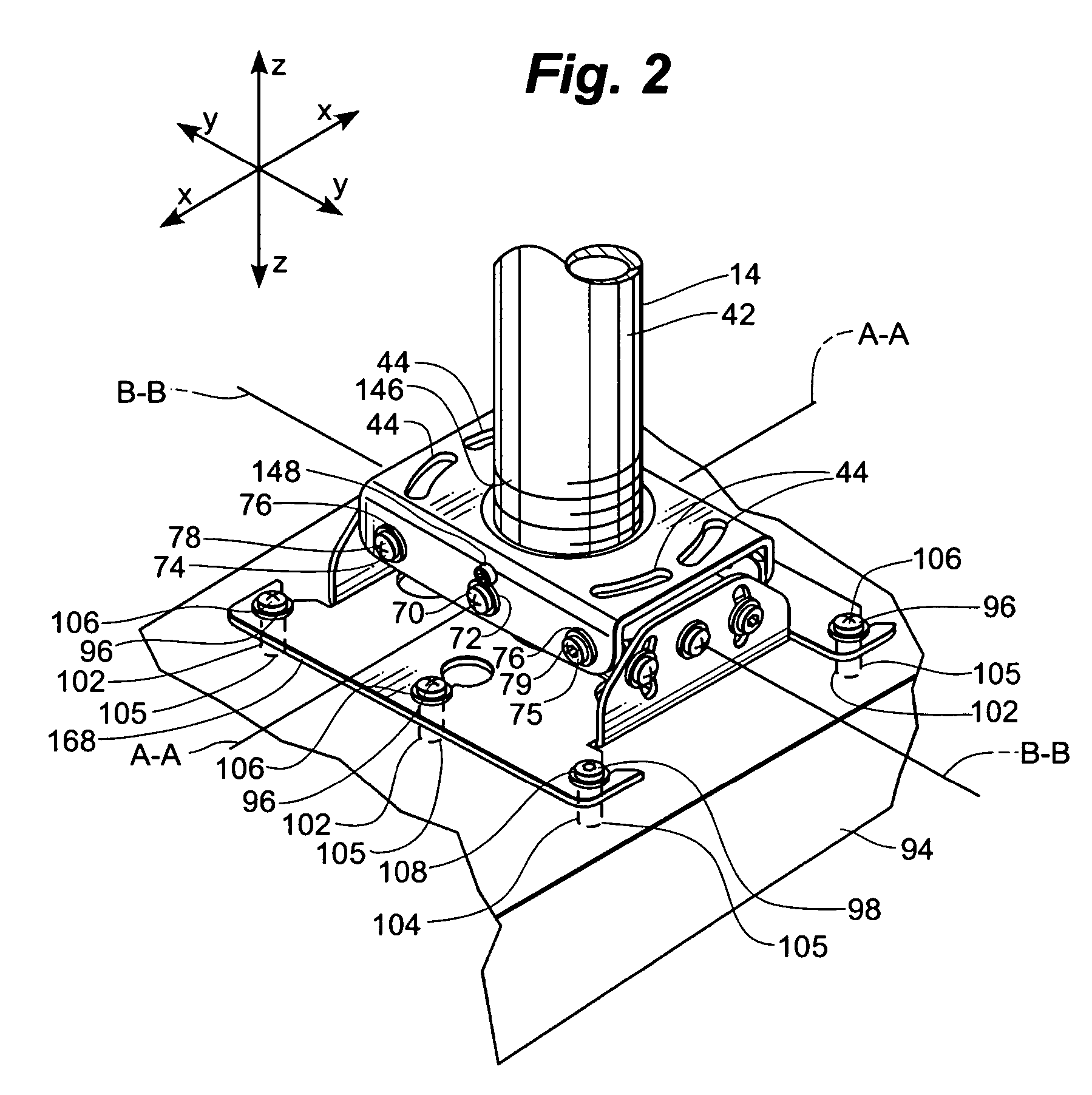
[0032]FIG. 2 designates, for reference purposes, the relative directions of x-y-z coordinates as applied to the mounting system 10. Any reference herein to rotation about an x-axis or “roll” movement, a y-axis or “pitch” movement, or a z-axis or “yaw” movement, relates to these coordinate axes. The y-axis is oriented fore-and-aft relative to a visual projector attached to the mounting system, the z-axis is vertical and the x-axis is perpendicular to the z-axis and the y-axis, and is oriented laterally from side-to-side of the projector.

[0033]Adjustable bracket 12 generally includes device interface bracket 18 and suspension member interface 20. Device interface bracket 18 includes planar portion 22 and a pair of spaced-apart upwardly projecting flanges 24. Each flange 24 has a central hole 26 and a pair of opposing curved slots 28 surrounding hole 26.

[0...


PUM


Abstract

An adjustable tamper-resistant overhead mounting system for a projector. The system includes brackets attachable to the projector and a suspension member attached to an overhead structure. At least one tamper resistant fastener is used at each connection of the brackets, the projector and the suspension member, to deter theft and tampering. The arrangement of the brackets may enable easy adjustable positioning of the projector about pitch, roll and yaw axes. The projector may also be enclosed in an enclosure system to protect against contact by foreign objects. The enclosure is adapted to be installable without removing the projector or otherwise disturbing the mounting system.

Description

RELATED APPLICATIONS[0001]This application claims the benefit of U.S. Provisional Patent Application Ser. No. 60 / 462,391 filed Apr. 11, 2003, the same being hereby fully incorporated herein by reference.FIELD OF THE INVENTION[0002]The present invention relates to mounting systems for visual projectors, and more specifically, to tamper resistant mounting systems for projectors.BACKGROUND OF THE INVENTION[0003]Visual projection systems are commonly used for displaying and presenting visual information to groups of people. Such visual projection systems typically include a projector unit and a projection screen.[0004]In spaces such as classrooms, conference rooms, and public assembly halls, where the space is often used for presentations, it is common that the projector unit be installed as a more or less permanent fixture in the space. Often, the projector will be suspended from an overhead structure, such as a building floor / ceiling assembly or roof, in order to give the projector an...

Claims


Application Information

Patent Timeline
Patent Type & Authority Patents(United States)
IPC IPC(8): F16M13/00F16M11/04F16M11/10H04N5/74H04N13/02
CPCF16M11/04F16M11/041F16M11/10F16M11/2071F16M13/02H04N5/7491F16M11/12Y10S248/917
Inventor DITTMER, JAYBREMMON, JEFF
Owner LEGRAND AV INC
Learn More