Sunroof panel for a vehicle

a technology for sunroof panels and vehicles, applied in the direction of roofs, mechanical equipment, transportation and packaging, etc., can solve the problems of not being able to guarantee the sealing performance at the portion of the sunroof panel, the sunroof panel does not look good, and the sealing performance cannot be said to be necessarily satisfactory

Active Publication Date: 2007-01-02
TOYOTA IND CORP
View PDF5 Cites 6 Cited by
  • Summary
  • Abstract
  • Description
  • Claims
  • Application Information

AI Technical Summary

Benefits of technology

[0009]The present invention is made to solve the problems described above. It is an object of the present invention to provide a sunroof panel in which the sealing performance is secured without damaging the appearance of the panel even when the panel expands and contracts due to temperature change.

Problems solved by technology

However such a sunroof panel does not look good because the weather strip can be seen from the outside of the vehicle.
However, the sunroof panel of JP 05-213072 A has the following problems.
Accordingly, the sealing performance cannot be said to be necessarily satisfactory.
In this case, the sealing performance cannot be secured at that portion.

Method used


Image

  • Sunroof panel for a vehicle
  • Sunroof panel for a vehicle
  • Sunroof panel for a vehicle

Examples


first embodiment

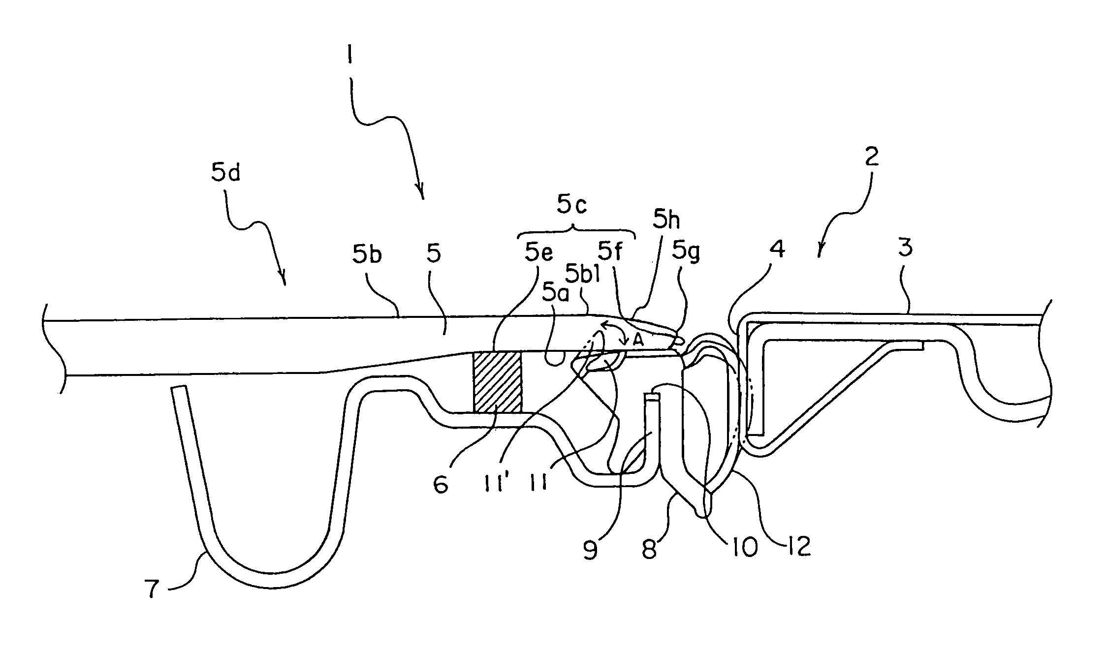
[0017]Referring to FIG. 1, a sunroof panel 1 according to a first embodiment of the present invention is fitted into an opening portion 4 so as to be slidable. The opening portion 4 is formed in a body 3 of a vehicle roof 2.

[0018]The sunroof panel 1 is composed of a resin panel 5 and a weather strip 8. The resin panel 5 is a plate-like resin panel and has a vehicle interior surface 5a facing the interior of the vehicle and a vehicle exterior surface 5b facing the exterior of the vehicle, which are substantially parallel to each other. The resin panel 5 is attached to a frame 7 by means of a urethane adhesive 6. The resin panel 5 has a peripheral portion 5c, which extends from a portion 5e sticking to the urethane adhesive 6 to a side face 5f, and a central portion 5d surrounded by the peripheral portion 5c. The peripheral portion 5c is thinner than the central portion 5d.

[0019]The side face 5f of the resin panel 5 is formed so as to be inclined inwardly toward the vehicle interior ...

second embodiment

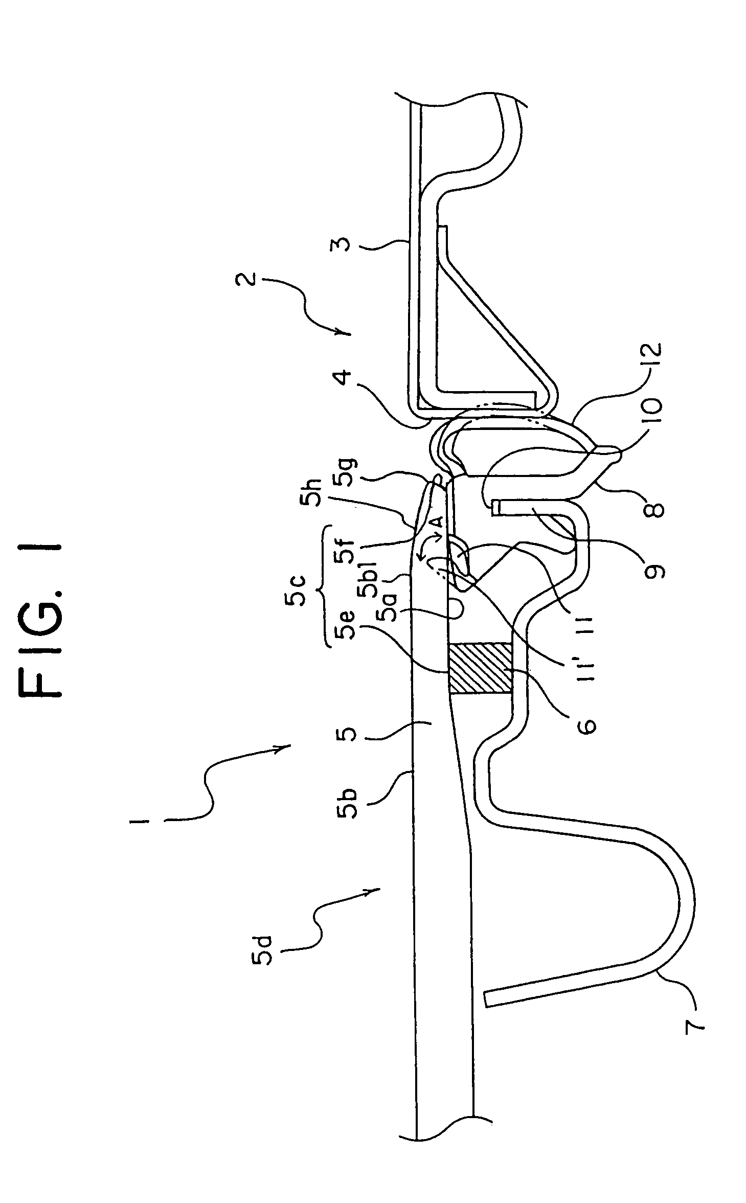
[0028]Referring to FIG. 2, a sunroof panel according to a second embodiment of the present invention will be described. It should be noted that in the following embodiments, components that are the same as or similar to those described in the first embodiment are denoted by the same symbols, and therefore the detailed description thereof is omitted.

[0029]As shown in FIG. 2, a sunroof panel 20 has a lip portion 23 whose shape is different from that of the lip portion in the first embodiment.

[0030]A recess 21 is formed in the weather strip 8 that is made to abut against the vehicle interior surface 5a of the resin panel 5. A urethane adhesive 22 is provided within the recess 21 for sealing between the resin panel 5 and the weather strip 8. In this case, the recess 21 and the urethane adhesive 22 constitute the lip portion 23.

[0031]As described above, because the recess 21 is formed in the weather strip 8 and the urethane adhesive 22 is provided within the recess 21, as in the first em...

third embodiment

[0032]Referring to FIG. 3, a sunroof panel according to a third embodiment of the present invention will be described.

[0033]As shown in FIG. 3, a sunroof panel 30 has a lip portion 33 whose shape is different from that of the lip portion in the first embodiment.

[0034]The weather strip 8 has a surface 8a that is exposed to a space 31 formed by the resin panel 5 and the frame 7. An arm portion 32 extending upward is formed integrally with the weather strip 8 on the surface 8a. The lip portion 33 is provided at the end of the arm portion 32. A force applied to the lip portion 33 from above causes the arm portion 32 to move elastically.

[0035]When the resin panel 5 is attached to the frame 7, the vehicle interior surface 5a is made to abut against both the weather strip 8 and the lip portion 33. A force is applied to the lip portion 33 downwardly by the resin panel 5, and the arm portion 32 moves elastically so as to absorb the force. Thus, the lip portion 33 seals between the resin pane...


PUM


Abstract

A sunroof panel is composed of a resin panel and a weather strip. The resin panel is a plate-like resin panel and has a vehicle interior surface and a vehicle exterior surface, which are substantially parallel to each other. The resin panel is attached to a frame by means of a urethane adhesive. The resin panel has a peripheral portion, which extends from a portion sticking to the urethane adhesive to a side face, and a central portion surrounded by the peripheral portion. The peripheral portion is thinner than the central portion. The side face of the resin panel is formed so as to be inclined inwardly toward the vehicle interior surface. An approach-R portion is formed on a peripheral portion of the vehicle exterior surface.

Description

BACKGROUND OF THE INVENTION[0001]1. Field of the Invention[0002]The present invention relates to a sunroof panel for a vehicle.[0003]2. Description of the Related Art[0004]JP 05-185839 A discloses a conventional sunroof panel of this type, which is constructed as follows: a resin panel is attached to a frame by means of an adhesive, and a weather strip is fitted so as to straddle both the resin panel and the frame. However such a sunroof panel does not look good because the weather strip can be seen from the outside of the vehicle.[0005]On the other hand, JP 05-213072 A discloses a sunroof panel whose weather strip cannot be seen from the outside, making the panel attractive. FIG. 4 is a cross sectional view of this sunroof panel. A body 42 of a vehicle roof 41 has an opening portion 43. A sunroof panel 44 is fitted into the opening portion 43 so as to be slidable. The sunroof panel 44 is composed of a resin panel 45 and a weather strip 46. A peripheral portion of the opening portio...

Claims


Application Information

Patent Timeline
Patent Type & Authority Patents(United States)
IPC IPC(8): B60J10/12B60J7/02B60J7/043B60J10/82
CPCB60J10/12B60J7/043B60J10/82
Inventor IIMORI, YASUSHIOAMI, KOTAROYANO, YOJIKAGOTANI, YUSUKE
Owner TOYOTA IND CORP
Why Eureka
Try Eureka