Motor

a technology of motors and bearings, applied in the field of motors, can solve the problems of lower bearings b>62/b> damage, bearing damage, etc., and achieve the effect of improving the sealing performance of the motor, ensuring sealing performance, and efficient manufacturing

Active Publication Date: 2020-10-08
LG INNOTEK CO LTD
View PDF0 Cites 3 Cited by
  • Summary
  • Abstract
  • Description
  • Claims
  • Application Information

AI Technical Summary

Benefits of technology

[0042]A motor according to embodiments which includes the above components can prevent a bearing from being damaged as well as secure sealing performance when a rotor is assembled inside a stator.
[0043]To this end, in the motor, the rotor can be installed inside a housing without a damage of the bearing using a groove formed on an outer circumferential surface of a cover.
[0044]Here, sealing performance of the motor can be improved by eliminating a hole at a bottom surface of the housing.
[0045]Also, since it is unnecessary to apply an additional sealing member due to the hole being eliminated, the motor can be efficiently manufactured during mass production. That is, although a curing time of the sealing member is necessary when the sealing member is applied, since it is possible to omit a procedure of applying the sealing member, motor productivity can be increased.
[0046]In the motor according to embodiments which includes the above components, an assembling position of the cover can be determined using positions of the groove formed in the cover and a groove formed in a busbar.
[0047]Also, when the cover is coupled to the housing, a size of the motor in an axial direction can be reduced using a second groove of the cover.

Problems solved by technology

However, a problem occurs in that a bearing is damaged during a process of assembling a rotor inside a stator disposed in a housing having no a central hole.
Accordingly, a problem is present in that the lower bearing 62 is damaged.

Method used


Image

  • Motor
  • Motor
  • Motor

Examples


embodiment 1

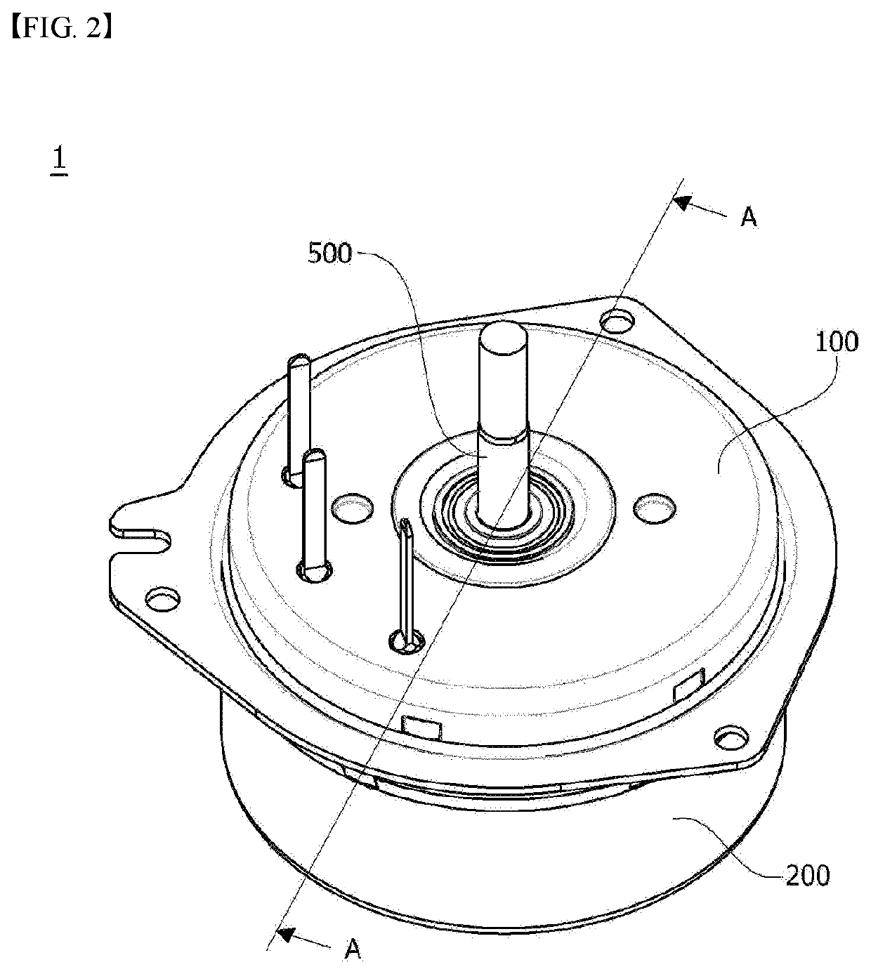
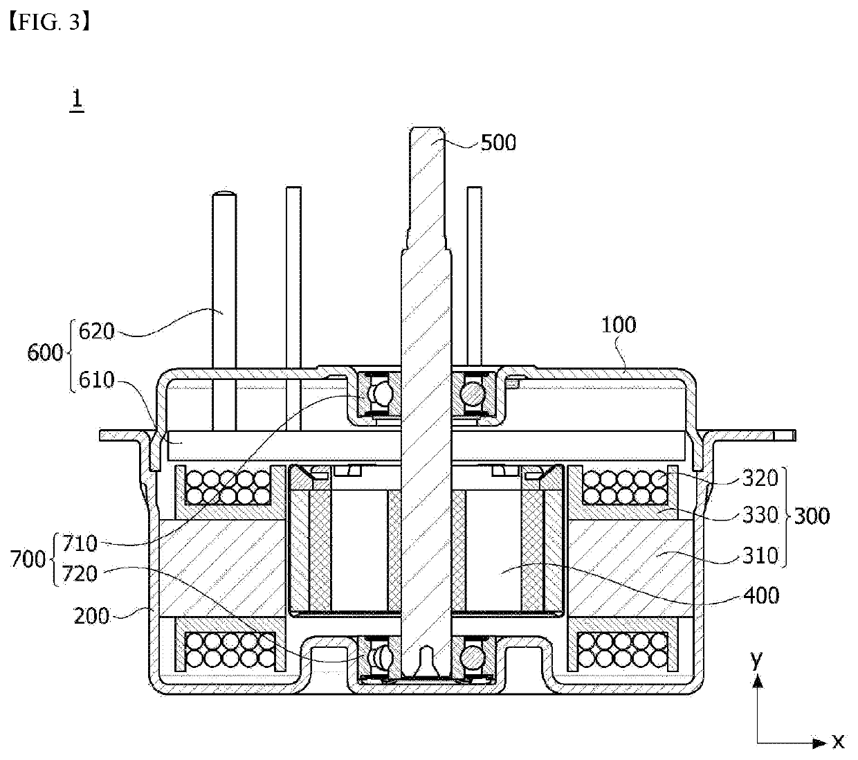
[0092]FIG. 2 is a perspective view illustrating a motor according to an embodiment, and FIG. 3 is a cross-sectional view of a motor according to a first embodiment taken along line A-A′ of FIG. 2. Here, an x direction shown in FIG. 3 means a radial direction, and a y direction means an axial direction.

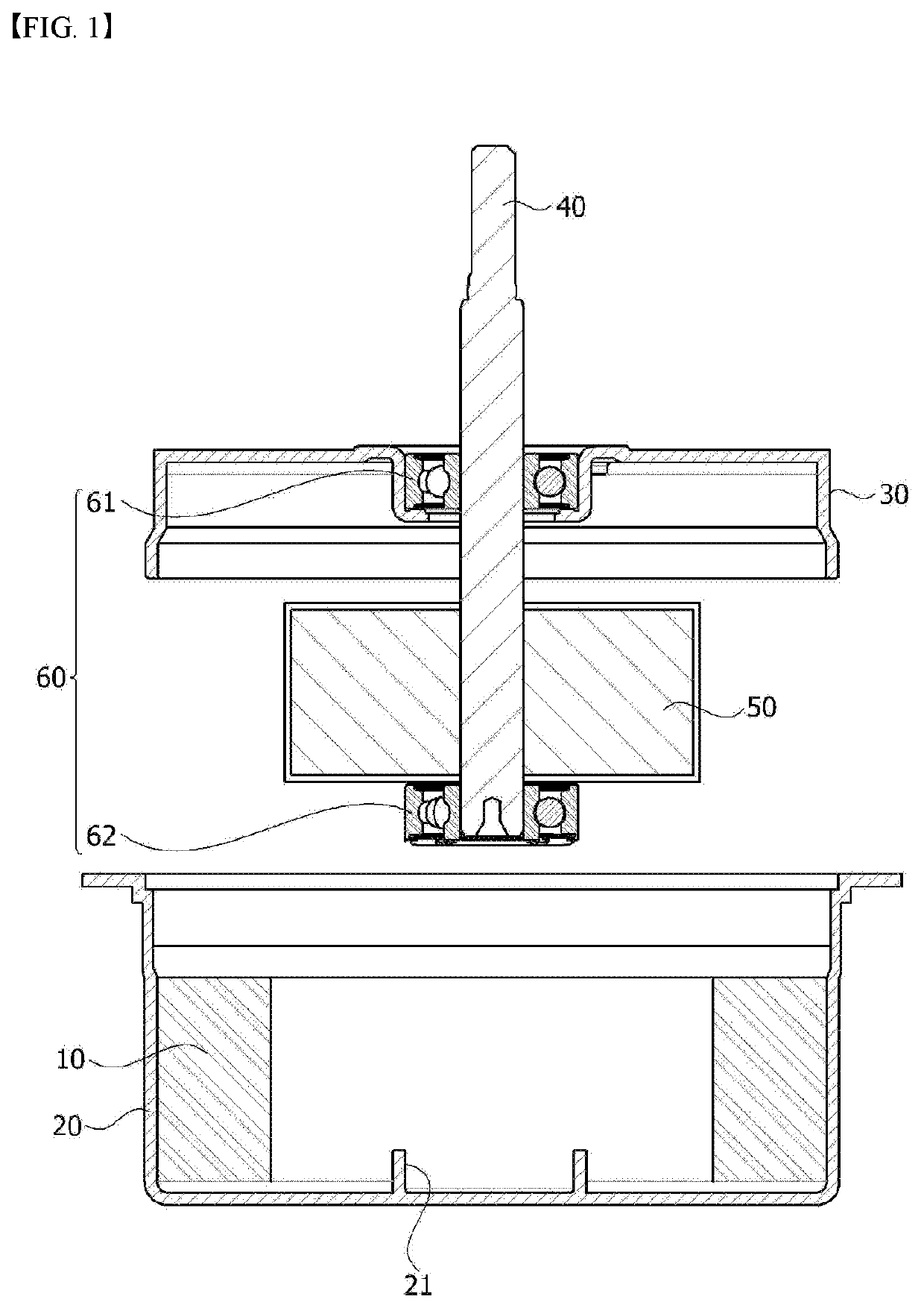
[0093]Referring to FIGS. 1 and 2, a motor 1 according to the first embodiment may include a cover 100, a housing 200 disposed below the cover 100, a stator 300 disposed inside the housing 200, a rotor 400 disposed inside the stator 300, a shaft 500 rotating with the rotor 400, a busbar 600 disposed above the stator 300, and a bearing 700 disposed on an outer circumferential surface of the shaft 500. Here, the bearing 700 may include, depending on positions, an upper bearing 710 disposed on an upper part of the shaft 500 and a lower bearing 720 disposed on a lower part thereof.

[0094]The cover 100 and the housing 200 may form an exterior of the motor 1. Here, the housing 200 may be forme...

embodiment 2

[0154]FIG. 11 is a cross-sectional view of a motor according to a second embodiment. Here, FIG. 11 is a cross-sectional view taken along line A-A of FIG. 3.

[0155]Hereinafter, in a description of a motor 1a according to the second embodiment, since components equal to those of the motor 1 according to the first embodiment are referred to with the same reference numerals, a detailed description thereof will be omitted.

[0156]Referring to FIGS. 11, the motor la according to the second embodiment may include the cover 100, a housing 200a disposed below the cover 100, the stator 300 disposed inside the housing 200a, the rotor 400 disposed inside the stator 300, the shaft 500 rotating with the rotor 400, the busbar 600 disposed above the stator 300, the bearing 700 disposed on the outer circumferential surface of the shaft 500, and a cap 800 disposed below the housing 200a.

[0157]In comparison to the motor 1 according to the first embodiment, the motor 1a according to the second embodiment...

embodiment 3

[0174]FIG. 16 is a perspective view illustrating a motor according to a third embodiment, FIG. 17 is a cross-sectional view illustrating the motor according to the third embodiment, and FIG. 18 is an exploded-perspective view illustrating the motor according to the third embodiment. Here, FIG. 17 is a cross-sectional view taken along line A-A of FIG. 16. Here, an x direction shown in FIG. 17 means a radial direction, and a y direction means an axial direction. Also, the axial direction and the radial direction are perpendicular to each other. Here, the axial direction may be a longitudinal direction of the shaft 1500.

[0175]Referring to FIGS. 16 to 18, a motor 1b according to the third embodiment may include a cover 1100, a housing 1200 disposed below the cover 1100, a stator 1300 disposed inside the housing 1200, a rotor 1400 disposed inside the stator 1300, a shaft 1500 rotating with the rotor 1400, a busbar 1600 disposed above the stator 1300, and a bearing 1700 disposed on an out...


PUM


Abstract

An embodiment relates to a motor comprising: a shaft; a rotor which is coupled to the shaft; a stator which is disposed outside the rotor; a housing which accommodates the rotor and the stator and has an opening formed at one side thereof; and a cover which covers the opening, wherein the cover comprises a cover plate portion; and a side wall which extends axially from the cover plate portion, and at least three grooves are formed in the side wall. Accordingly, the motor according to the embodiment can guarantee the sealing performance while preventing the bearing from being damaged when the rotor is assembled on the inside of the stator.

Description

TECHNICAL FIELD[0001]Embodiments relate to a motor.BACKGROUND ART[0002]A motor is a device which converts electrical energy into rotational energy using a force that a conductor receives in a magnetic field. Recently, as a use of a motor has increased, a role of a motor has become more important. Particularly, as electric apparatuses in a vehicle rapidly increase, demands for motors applied to a steering system, a brake system, a design system, and the like are significantly increasing.[0003]In general, a motor includes a shaft formed to be rotatable, a rotor coupled to the shaft, and a stator fixed inside a housing, in which the stator is installed along a circumference of the rotor with a gap therebetween. Also, a coil configured to form a rotating magnetic field is wound on the stator so as to cause an electrical interaction with the rotor and induce rotation of the rotor. As the rotor rotates, the shaft rotates and generates a driving force.[0004]Also, a busbar electrically conn...

Claims


Application Information

Patent Timeline
Patent Type & Authority Applications(United States)
IPC IPC(8): H02K5/10H02K3/52H02K5/173
CPCH02K3/522H02K5/10H02K5/1732H02K2203/09H02K5/22H02K2213/03H02K5/15H02K15/16
Inventor PARK, KYUNG SANGKU, JU HWAN
Owner LG INNOTEK CO LTD
Why Eureka
Try Eureka