Sealing structure and compressor

a sealing structure and compressor technology, applied in the direction of machines/engines, liquid fuel engines, positive displacement liquid engines, etc., can solve the problems of increasing vibration and noise, and deteriorating the reliability of the compressor, so as to secure the sealing performance and improve the productivity , the effect of not increasing the number of components

Active Publication Date: 2013-12-03
DAIKIN IND LTD
View PDF6 Cites 3 Cited by
  • Summary
  • Abstract
  • Description
  • Claims
  • Application Information

AI Technical Summary

Benefits of technology

[0009]The present invention was done to solve the problem above, and an objective of the present invention is to provide a sealing structure and a compressor, which are capable of securing the sealing performance between the head component and the muffler component without increasing the machining accuracy of the mounting surfaces of the head component and the muffler component and without increasing the number of components.
[0069]According to the fifteenth aspect of the invention, it is possible to secure the sealing performance between the head component and the muffler component without precisely processing the mounting surfaces of the head component and the muffler component and without increasing the number of components.

Problems solved by technology

However, the conventional sealing structure 650 of FIG. 14(a) is disadvantageous in that, when a mounting surface of the muffler component 639 and a mounting surface of the head component 638 are not flat enough, a gap is formed between a boss portion 638c of the head component 638 and the muffler component 639 as shown in FIG. 14(b), and refrigerant leaks out from the gap.
The leakage of refrigerant induces increase in vibration and noise of the compressor and obstructs lubricating oil from being supplied to a slide portion because the lubricating oil stored in the bottom portion of the closed container foams, and hence the reliability of the compressor is deteriorated.
The rotary compressor of Japanese Unexamined Patent Publication No. 215993 / 1990, however, is disadvantageous in that it is necessary to increase the number of components because a conical claw washer is required to secure the sealing performance between the boss portion and the muffler component.
Furthermore, since the process of machining of the mounting surface of the head component and the mounting surface of the muffler component is unnecessary, cost increase associated with the machining does not occur.

Method used


Image

  • Sealing structure and compressor
  • Sealing structure and compressor
  • Sealing structure and compressor

Examples


first embodiment

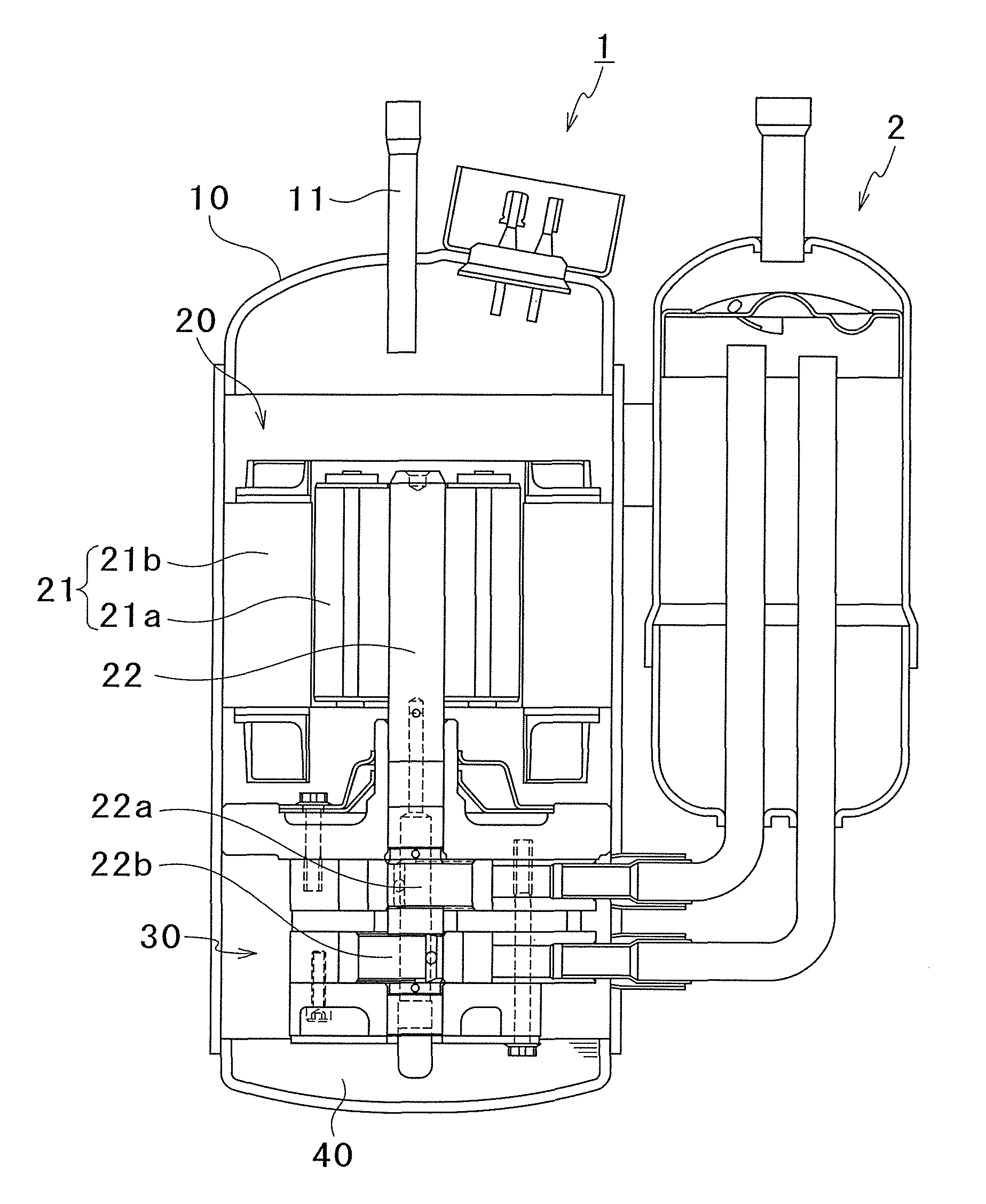
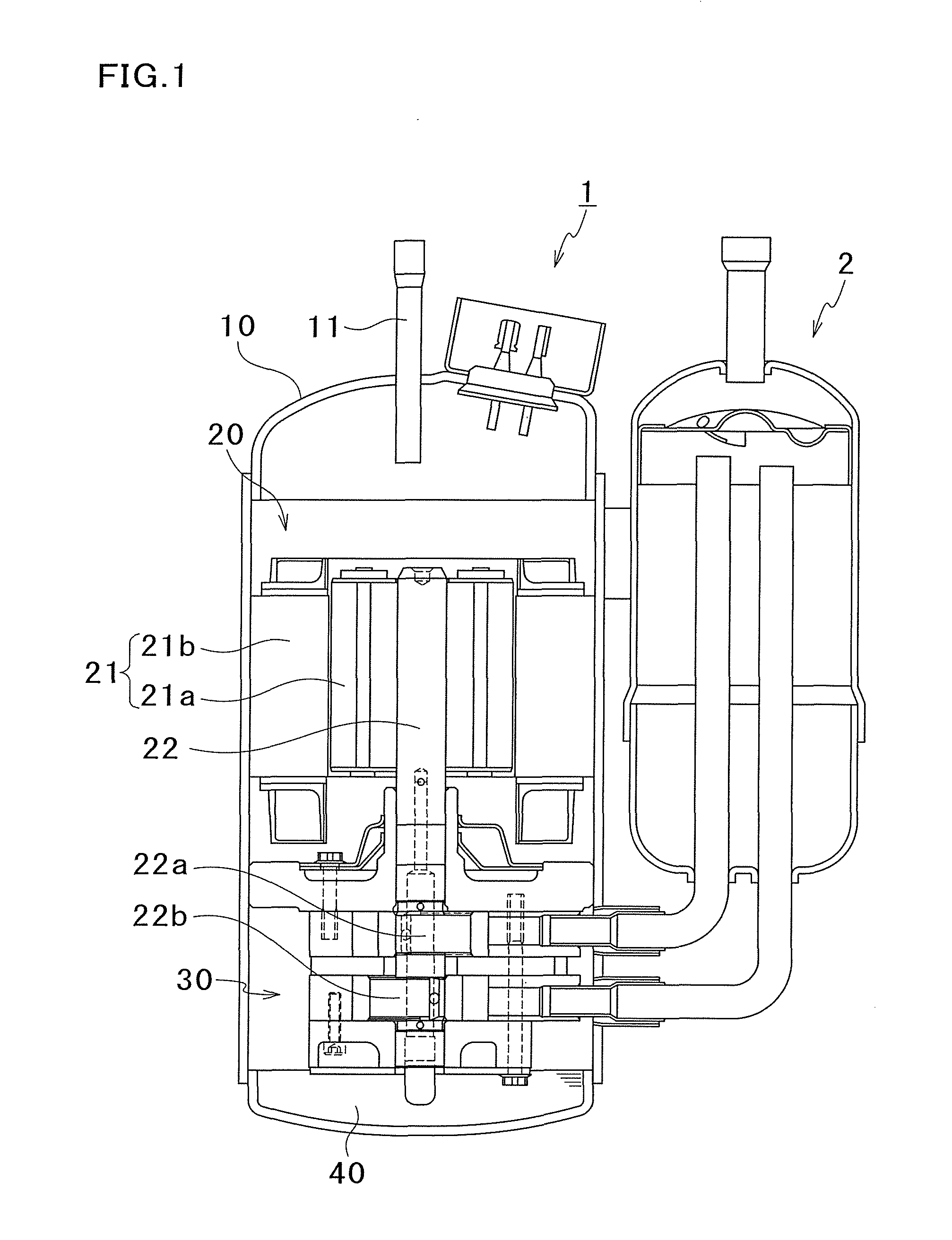
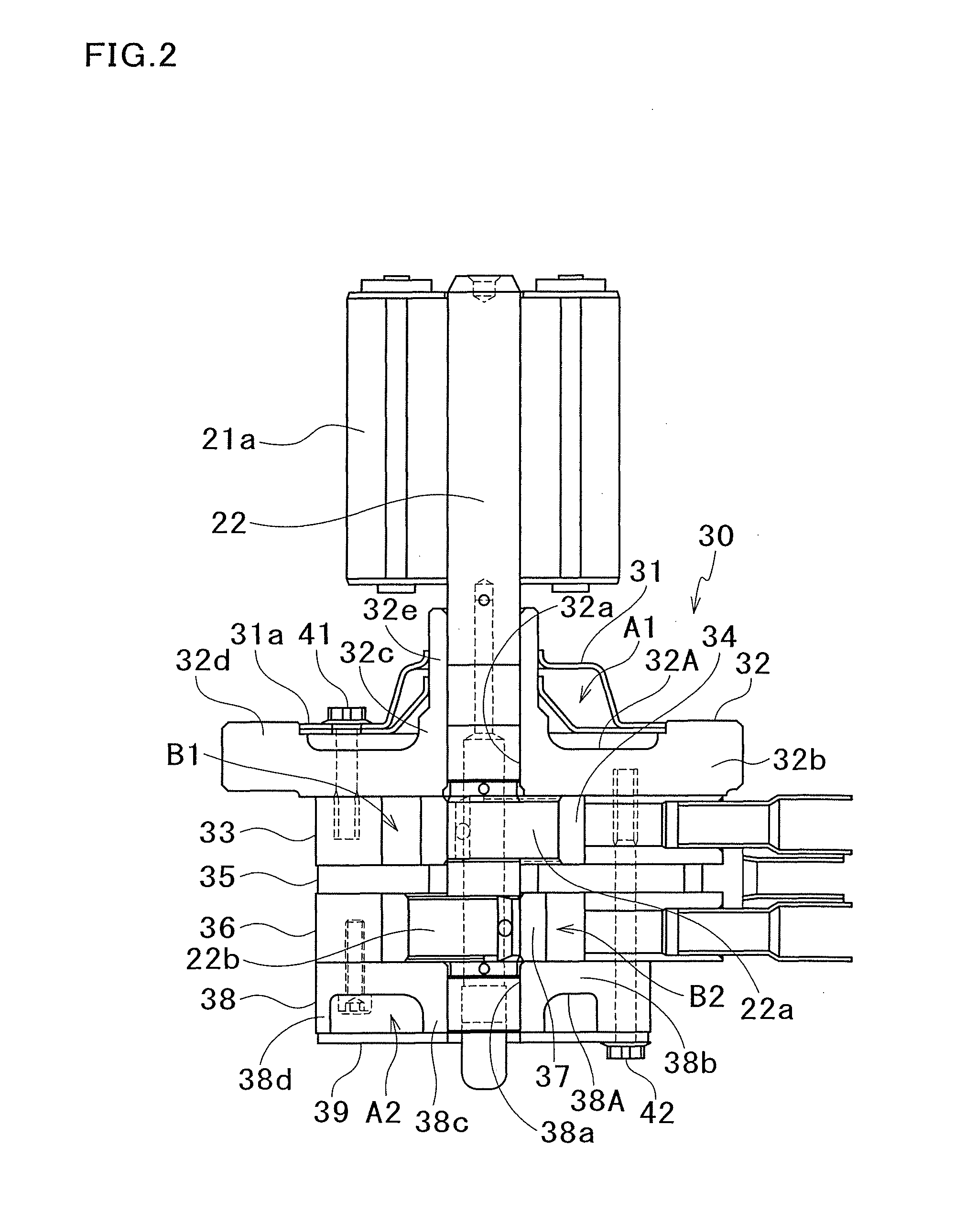
[0085]FIG. 1 is a cross section of a rotary compressor and an accumulator of First Embodiment according to present invention. FIG. 2 is a cross section of the drive mechanism and the compression mechanism of the rotary compressor of FIG. 1. FIG. 3 schematically shows a sealing structure. FIG. 4 schematically shows a rear head and a rear muffler before fastened. FIG. 5 is a plan view of the rear head. FIG. 6 is a plan view of the rear muffler. Referring to FIGS. 1 to 6, details of a rotary compressor 1 of First Embodiment will be given.

[0086]As shown in FIG. 1 and FIG. 2, the rotary compressor 1 includes a closed casing 10 and this closed casing 10 houses therein a drive mechanism 20 and a compression mechanism 30. This rotary compressor 1 is a so-called high-pressure dome type compressor, and the compression mechanism 30 is disposed below the drive mechanism 20 in the closed casing 10. In the lower part of the closed casing 10 is stored lubricating oil 40 supplied to each slide port...

second embodiment

[0118]FIG. 8 schematically shows a sealing structure of a rotary compressor of Second Embodiment according to the present invention. FIG. 9 schematically shows a rear head and a rear muffler before fastened. Second Embodiment is different from First Embodiment in which the entirety of the end surface of the boss portion of the rear head is arranged to be further from the main body than the plane including the end surface of the side wall. Second Embodiment is arranged so that the peripheral portion of the opening of the rear muffler is shaped to protrude from a part contacting the end surface of the side wall. Since Second Embodiment is identical with First Embodiment except the arrangement of the rear head and the rear muffler, the same reference numerals are assigned to components having substantially identical arrangements as those of First Embodiment, and such components are not detailed again.

[0119]A rear head 138 is provided below the rear cylinder 36 to block off the lower op...

examples

[0131]Now, an experiment carried out for determining the range of the value P in the relation (1) above will be described. In this experiment, the value P was calculated by the relation above and the occurrence of locking in the rotary compressor was checked, while the thickness (mm) of the rear muffler and the level difference L1 (mm) between the boss portion and the side wall of the rear head were changed. Table 1 shows the result of the experiment. It is noted that the distance a between the axial center of the rear head and a part of the inner periphery of the fastening hole of the side wall which part is closest to the axial center of the rear head was set to 28 mm, the distance b between the axial center of the rear head and the outer periphery of the boss portion was set to 13 mm, and the flexibility factor α with respect to the diameter ratio b / a was set to 0.1.

[0132]

TABLE 1

[0133]Table 1 above shows that the rotary compressor can operate without the occurrence of locking, wh...


PUM


Abstract

A sealing is arranged between a rear head having an ejection port configured and arranged to eject compressed refrigerant and a rear muffler disposed so that a muffler space is formed between the rear muffler and the rear head. The rear head includes a main body having a bearing hole, an annular boss portion protruding from the main body and circumscribing the bearing hole, and an annular side wall protruding from the main body and circumscribing the boss portion. The rear muffler has an opening and is fastened to the end surface of the side wall so that the peripheral portion of the opening contacts the end surface of the boss portion. Preferably, the end surface of the boss portion has a part entirely further from the main body than the end surface of the side wall.

Description

CROSS-REFERENCE TO RELATED APPLICATIONS[0001]This U.S. National stage application claims priority under 35 U.S.C. §119(a) to Japanese Patent Application No. 2007-306931, filed in Japan on Nov. 28, 2007, the entire contents of which are hereby incorporated herein by reference.TECHNICAL FIELD[0002]The present invention relates to a sealing structure between a head component having an ejection port ejecting compressed refrigerant and a muffler component which is provided so that a muffler space is formed between the head component and the muffler component, and also relates to a compressor having the sealing structure.BACKGROUND ART[0003]A typical rotary compressor includes a cylinder, a roller which rotates in a cylinder chamber of the cylinder, a head component having an ejection port by which refrigerant compressed by the rotation of the roller is ejected, and a muffler component which is provided so that a muffler space is formed between the head component and the muffler component...

Claims


Application Information

Patent Timeline
Patent Type & Authority Patents(United States)
IPC IPC(8): F04B49/00
CPCF04C18/3564F04C29/068F04C29/12F04C29/065F04C23/001F04C23/008F04C27/008
Inventor YUASA, KENICHIKAMIISHIDA, HIROKIKANAYAMA, TAKEHIRO
Owner DAIKIN IND LTD
Why Eureka
Try Eureka