Terminal fitting and a connector using such a terminal fitting

a technology of terminal fittings and connectors, which is applied in the direction of coupling contact members, coupling device connections, electrical devices, etc., can solve the problems of external matter striking and deforming the auxiliary springs, and achieve the effect of preventing the displacement of the springs

a technology of terminal fittings and connectors, which is applied in the direction of coupling contact members, coupling device connections, electrical devices, etc., can solve the problems of external matter striking and deforming the auxiliary springs, and achieve the effect of preventing the displacement of the springs

US7156704B2Inactive Publication Date: 2007-01-02SUMITOMO WIRING SYST LTD

Image

  • Terminal fitting and a connector using such a terminal fitting
  • Terminal fitting and a connector using such a terminal fitting
  • Terminal fitting and a connector using such a terminal fitting

Examples


Embodiment Construction

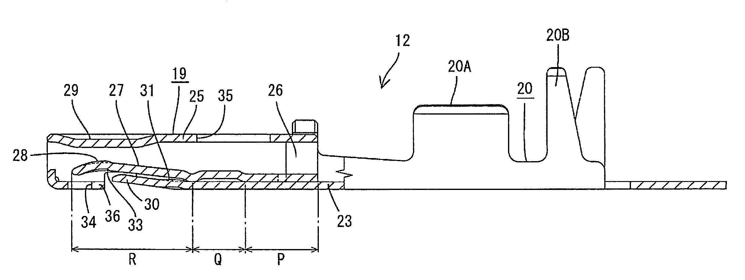
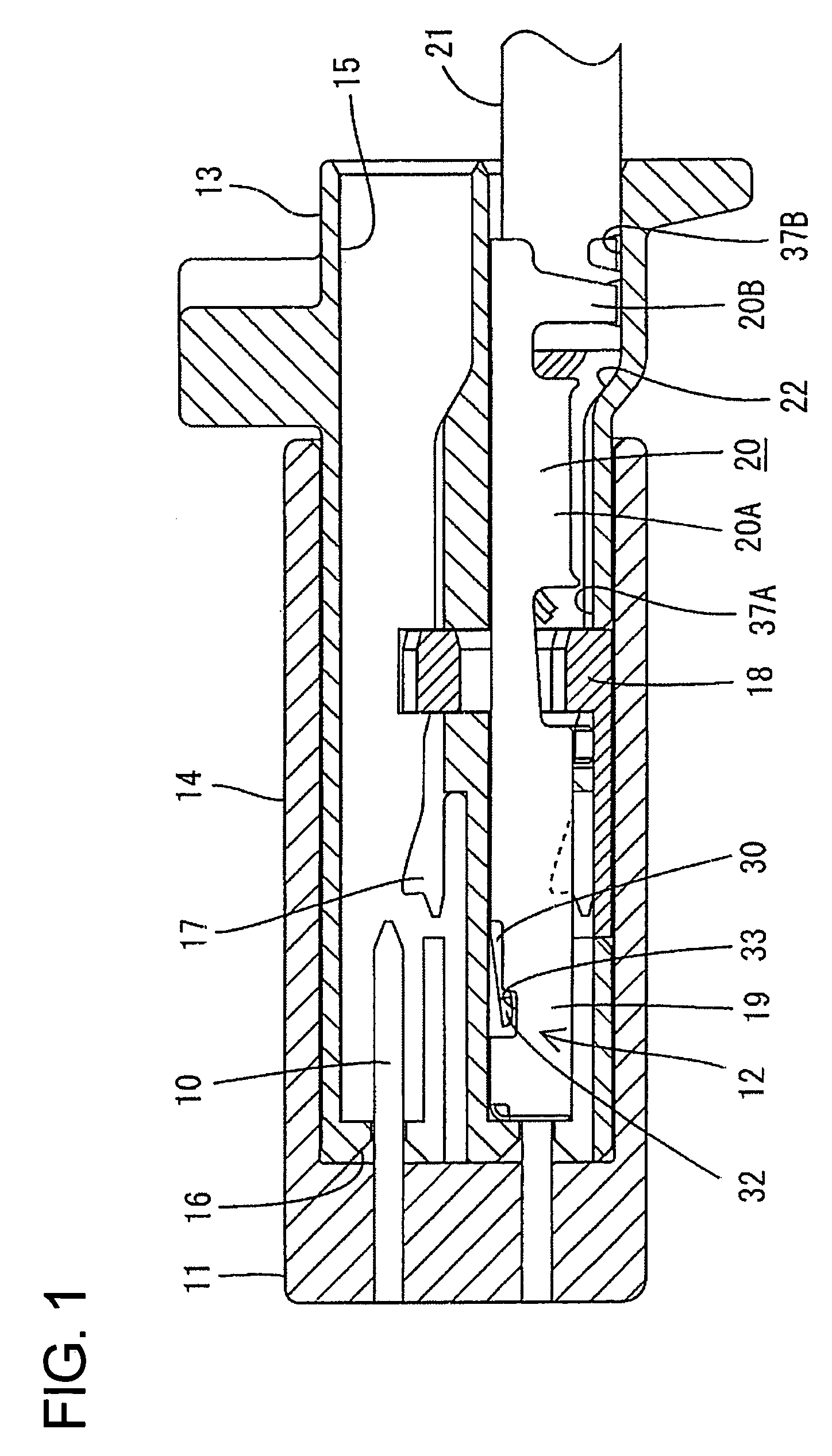
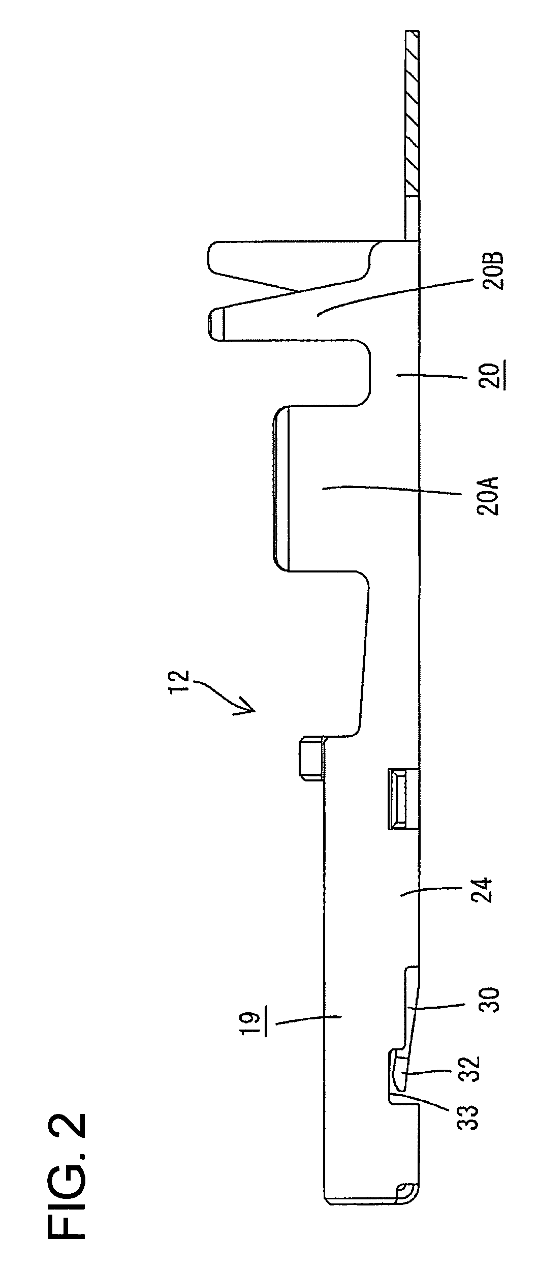
[0029]A connector assembly according to the invention has male terminal fittings 10 disposed at two stages in a male housing 11 and female terminal fittings 12 disposed at two stages in a female housing 13, as shown in FIGS. 1 to 9. The two housings 11, 13 are connectable with and separable from each other. In the following description, connecting directions of the housings 11, 13 are referred to as the forward directions. Reference is made to FIG. 1 concerning the vertical direction of the housing, but reference is made to FIGS. 2 and 7 for the vertical direction of the female terminal fitting 12.

[0030]As shown in FIG. 1, the male housing 11 is made e.g. of a synthetic resin and includes a receptacle 14 with an open front end. The male terminal fittings 10 are mounted through the rear wall of the receptacle 14 and project into the receptacle 14.

[0031]The female housing 13 is made e.g. of a synthetic resin and has cavities 15 for accommodating the female terminal fittings 12. Insert...


PUM


Abstract

A female terminal fitting (12) has tube (19) for receiving a male terminal fitting (10). A main spring (27) is cantilevered forwardly from the tube (19) and an auxiliary spring (30) is cantilevered forwardly at the outer side of the main spring piece (27). Stoppers (32) bulge out from the opposite sides of the auxiliary spring (30) for preventing the auxiliary spring (30) from being displaced up when the free end of the auxiliary spring (30) is thrust up from the outer side. Receiving portions (33) are left in the tube (19) during the forming of the auxiliary spring (30) and contact the stoppers (32). Thus, even if an external matter strikes against the auxiliary spring (30), the auxiliary spring (30) will not deform excessively in thrust-up direction.

Description

BACKGROUND OF THE INVENTION[0001]1. Field of the Invention[0002]The invention relates to a terminal fitting and a connector using such a terminal fitting.[0003]2. Description of the Related Art[0004]Japanese Unexamined Patent Publication No. H11-224709 discloses a terminal fitting with a tubular portion for receiving a mating terminal. A resiliently deformable spring piece is provided in the tubular portion and an auxiliary spring is a cantilevered forward at the outer side of the spring piece. The mating terminal is inserted into the tubular portion and deforms the spring piece. Thus, the deformed spring piece is urged resiliently against the mating terminal fitting to establish electrical connection. Additionally, the auxiliary spring contacts the spring piece from the outer side to reinforce the resilient force of the spring piece.[0005]However, the auxiliary spring piece is exposed at the side surface of the tubular portion in the above construction. As a result, external matter...

Claims


Application Information

Patent Timeline
02 Jan 2007
Publication
US7156704B2
IPC
H01R11/22
CPC
H01R13/113
Inventors
SHIMIZU, TOORU