Pressure monitor for cryoablation catheter

a technology of pressure monitor and catheter, which is applied in the field of cryoablation catheter devices and methods, can solve the problems of reducing the likelihood of catheter tip successfully navigating, increasing the tip size, and presenting a relatively harsh environment for pressure sensors

Active Publication Date: 2007-01-02
CRYOCOR
View PDF55 Cites 40 Cited by
  • Summary
  • Abstract
  • Description
  • Claims
  • Application Information

AI Technical Summary

Problems solved by technology

With the above in mind, there are several drawbacks associated with placing a pressure sensor directly in the expansion chamber of a cryocatheter.
First, such a positioning scheme uses up critical space at the distal tip of the catheter.
More specifically, placing the pressure sensor at the tip results in either a reduction in expansion chamber volume or an increase in catheter tip size.
On the other hand, increasing the tip size reduces the likelihood that the catheter tip can successfully navigate through the vasculature and reach the treatment site.
In addition to space considerations, the expansion chamber presents a relatively harsh environment for a pressure sensor.

Method used


Image

  • Pressure monitor for cryoablation catheter
  • Pressure monitor for cryoablation catheter

Examples


Embodiment Construction

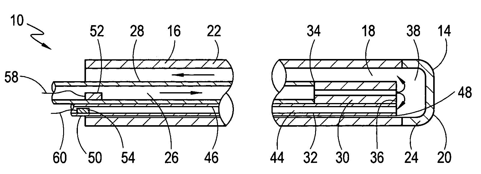
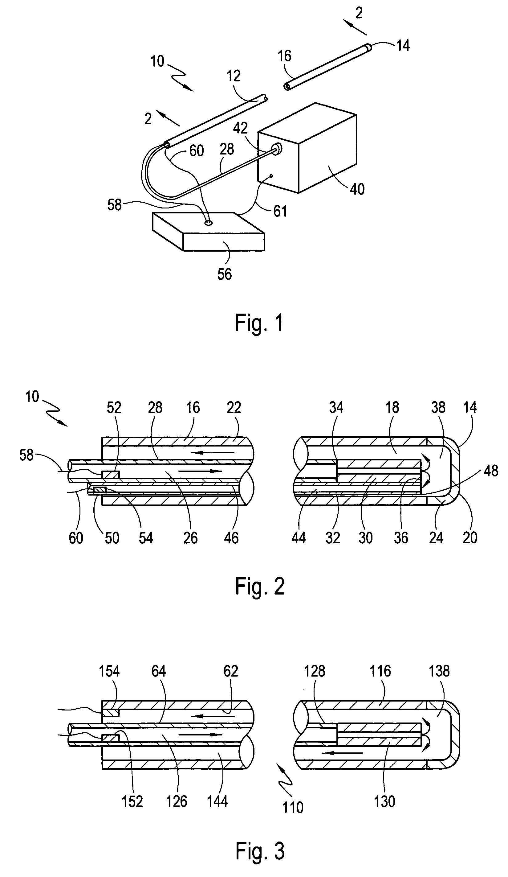
[0019]Referring to FIG. 1, a device for cryoablating tissue at an internal treatment site is shown and generally designated 10. As shown in FIG. 1, the device 10 includes a catheter 12, the distal end of which is typically inserted into the vasculature of a patient (not shown) and advanced to a treatment site. With the distal end of the catheter 12 positioned at a treatment site, an operative surface such as surface 14 can be cooled to a cryogenic temperature (e.g. minus −85 degrees Celsius) and placed in contact with selected internal tissue to cryoablate both contacted and surrounding tissue. Cryoablation of tissue can be performed for a variety of purposes including, but not limited to, the destruction or isolation of diseased tissue. In one application, cryoablation can be used to form conduction blocks to prevent unwanted electrical signals from originating or passing through a specific portion of a patient's body. For example, in one procedure that is useful in treating patien...


PUM


Abstract

A cryoablation device having a pressure monitoring system includes an elongated catheter tube that has a central lumen and is formed with a closed distal end. The distal end of a refrigerant supply line is positioned in the central lumen and distanced from the catheter tube's distal end to establish an expansion chamber therebetween. A return line, which can be established between the supply line and the catheter tube or can include a return tube, is provided to exhaust expanded refrigerant from the chamber. First and second pressure sensors are respectively positioned in the supply line upstream from the expansion chamber and in the return line. Typically, both sensors are positioned to remain at extracorporeal locations throughout a cryoablation procedure. Measured pressures are used together with the supply and return line dimensions to analytically estimate the chamber pressure and allow the expansion of refrigerant in the chamber to be monitored.

Description

FIELD OF THE INVENTION[0001]The present invention pertains generally to devices and methods for cryoablating internal tissue. More particularly, the present invention pertains to devices and methods for monitoring the pressure inside the expansion chamber of a cryoablation catheter. The present invention is particularly, but not exclusively, useful for monitoring pressures at the tip of a cryoablation catheter using pressure sensors that remain extracorporeally positioned during a cryoablation procedure.BACKGROUND OF THE INVENTION[0002]The non-invasive cryoablation of tissue within the vasculature (e.g. the veins, arteries and chambers of the heart) of a patient can be used to effectively destroy or isolate diseased tissue. For example, atrial fibrillation, which is a somewhat common heart condition, can be treated by cryoablating a circumferential band of tissue surrounding the ostium where a pulmonary vein connects with the left atrium to prevent abnormal electrical signals from r...

Claims


Application Information

Patent Timeline
Patent Type & Authority Patents(United States)
IPC IPC(8): A61B18/18A61B18/02A61B19/00
CPCA61B18/02A61B2019/464A61B2018/0262A61B2018/0212A61B2090/064
Inventor LENTZ, DAVID J.RYBA, ERIC
Owner CRYOCOR
Why Eureka
Try Eureka