Damping device

a technology of adamant device and a cylinder head, which is applied in the direction of shock absorbers, manufacturing tools, wing accessories, etc., can solve the problems of short operating distance, possible tilting/jamming of the piston in the cylinder head, and additional disadvantages of fluid medium, so as to achieve the effect of compact formation of the hammer devi

Inactive Publication Date: 2005-10-25
GRASS GMBH
View PDF39 Cites 42 Cited by
  • Summary
  • Abstract
  • Description
  • Claims
  • Application Information

AI Technical Summary

Benefits of technology

[0008]According to the invention each of the two damping elements are designed as pneumatic dampers and contain a compression chamber and an expansion chamber of variable volumes. The damping effect of the damping elements are affected by the guide canals, which steer the air distribution and air flow within and between the compr

Problems solved by technology

Likewise, the small overall height results in a short operating distance and, therefore, in connection with a fluid medium has a hard damping character.
Fluid medium additionally have the disadvantage of having possible leakages.
A further disadvantage results from the short slide surfaces and the possible tilting/jamming of the pistons in the cylinder.
These two-stage operations, which occur

Method used


Image

  • Damping device
  • Damping device
  • Damping device

Examples


Embodiment Construction

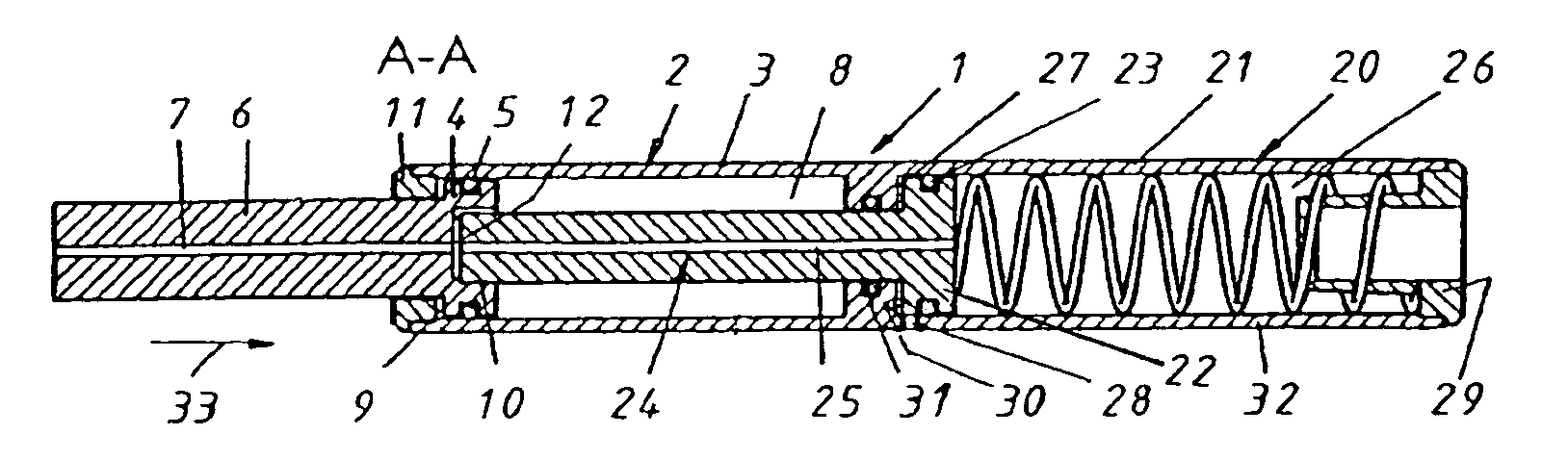
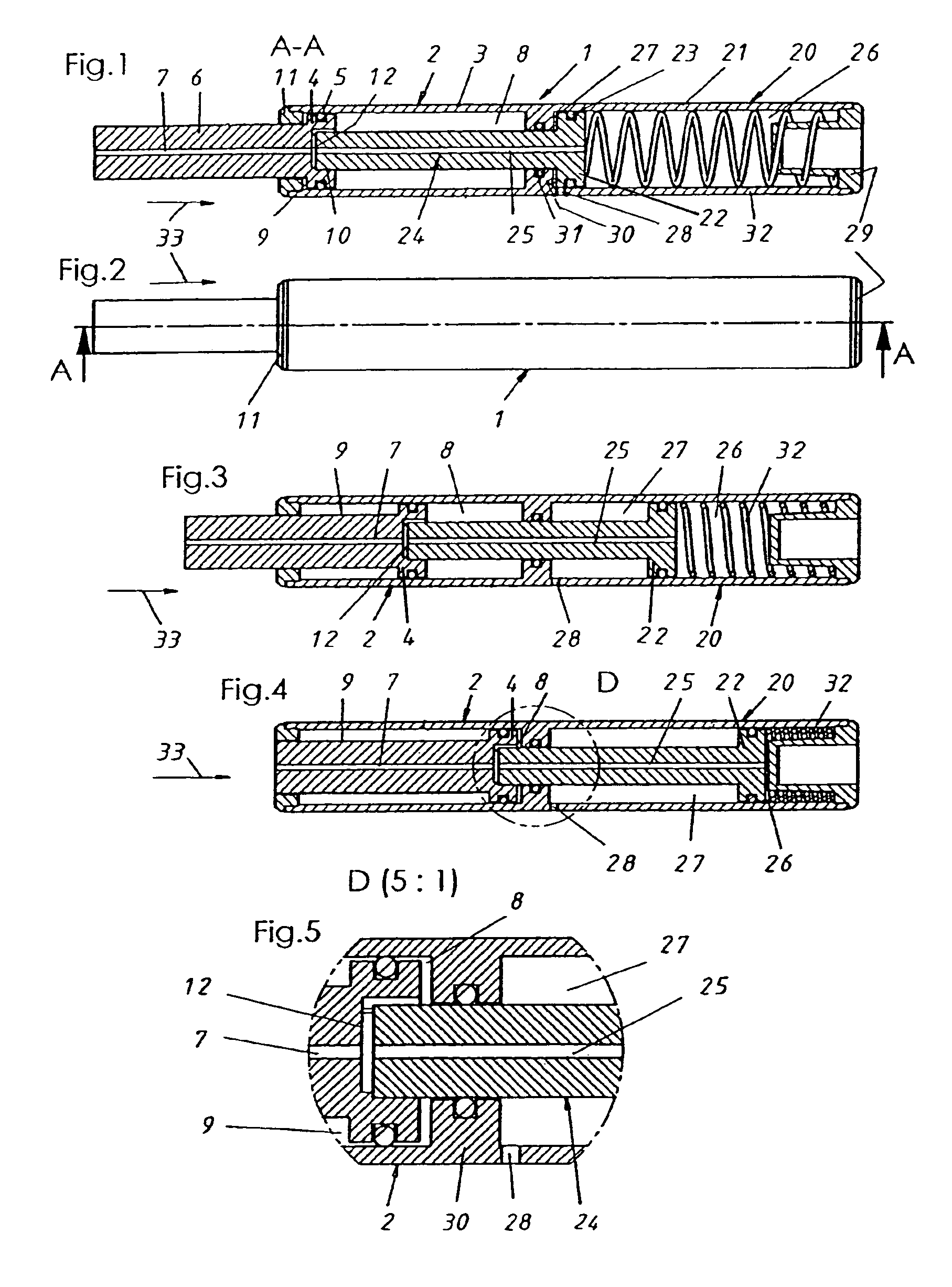
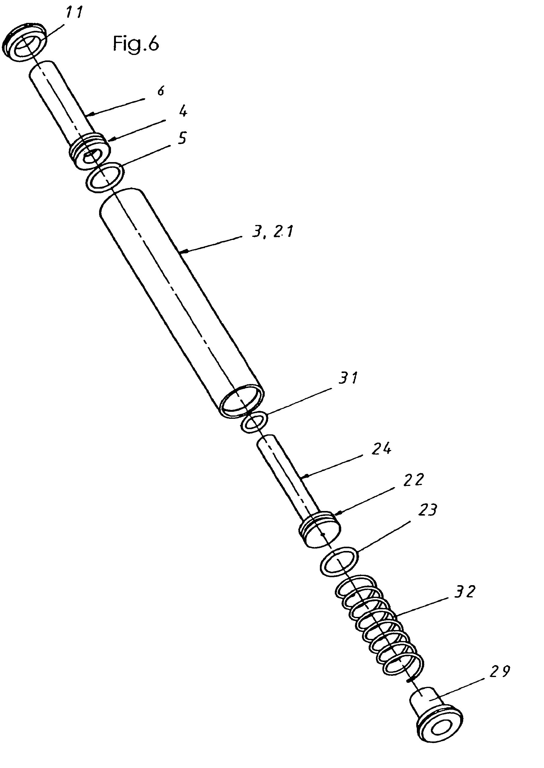
[0039]FIGS. 1 to 6 show a first embodiment of the invention. As shown in FIG. 1, the damping device (1) has two damping elements (2, 20) one located behind the other. Each damping element is designed as a pneumatic damper and includes a cylinder (3, 21) so that both cylinders (3, 21) have a common casing.

[0040]Inside the first cylinder (3) is a lengthwise movable first piston (4). Inside the second cylinder (21) is a lengthwise movable second piston (22).

[0041]Because of the pistons, each of the cylinder's (3, 21) partitions variable volumes, in each case a compression chamber (8 and / or 26) and in each case an expansion chamber (9 and / or 27). The pistons are guided (4, 22) sealing in the cylinders (3, 21); that means that with each damping element there is a seal (5 and / or 23) between the largest diameter of the respective piston and the inside diameter of the corresponding cylinder, which seals the respective compression chamber (8 and / or 26) opposite the corresponding expansion ch...


PUM


Abstract

The invention concerns a damping device for damping the kinetic energy of movable cabinet components, which has a first damping element with a first cylinder that has a first piston, which slides lengthwise in it, and at least one more (second) damping element with a second cylinder that has a second piston, which slides lengthwise in it. Both damping elements are located one behind the other in a serial arrangement and form an integral system. The invention is characterized by the fact that each of the two damping elements are each designed as pneumatic (air) dampers, and a compression chamber and an expansion chamber respectively contain variable volumes; whereby, the damping effects of the damping elements are affected by the guide canals, which control the air distribution and air flow within and between the compression chambers and/or expansion chambers.

Description

FIELD OF THE INVENTION[0001]The invention concerns a damping device, in particular for damping and / or absorbing the kinetic energy of movable cabinet components, as for example, doors, drawers or lifter-doors, according to the characteristics of the introductory clause of the patent claim 1.BACKGROUND OF THE INVENTION[0002]From the state of technology, damping devices of different designs are well known.[0003]DE 201 17 031 U1 shows a damping device with a fluid medium in the cylinders with pistons and piston rods and a small assembly depth. The cylinders are designed as telescopic cylinders; whereby, the center cylinder serves not only as pistons and not only as pressure cylinders, but also in this last case as pressure and / or working piston. The small overall height causes a large outside diameter and with it a large insertion bore hole. Likewise, the small overall height results in a short operating distance and, therefore, in connection with a fluid medium has a hard damping char...

Claims


Application Information

Patent Timeline
IPC IPC(8): E05F5/02E05F5/00E05F5/08E05F5/10F16F9/26F16F9/14F16F9/02
CPCE05F5/02E05F5/08E05F5/10F16F9/0209F16F9/26E05Y2201/21E05Y2201/212E05Y2201/256Y10T16/281E05Y2800/244E05Y2900/20E05Y2800/22E05Y2201/264
Inventor ZIMMER, MARTINTHALLNER, RAINERAHLFELD, JUERGENMUELLER, WOLFGANG
Owner GRASS GMBH
Why Eureka
Try Eureka