Sliding module for portable terminal

a portable terminal and sliding technology, applied in the field of sliding modules for portable terminals, can solve the problems of limited compactness of flip-type portable terminals, limited compactness of types, and limitations of compactness, and achieve the effect of reducing width

Active Publication Date: 2007-01-02
SAMSUNG ELECTRONICS CO LTD
View PDF7 Cites 15 Cited by
  • Summary
  • Abstract
  • Description
  • Claims
  • Application Information

AI Technical Summary

Benefits of technology

[0012]An object of the present invention is to provide a sliding module with a reduced width, so as to realize the compactness of a portable terminal.

Problems solved by technology

This type is limited with regard to compactness, which results from constant exposure of the keypad, i.e., a data input means, as well as ensuring a sufficient distance between the transceiver unit and the receiver unit.
However, the flip-type portable terminal is also limited in compactness due to ensuring the distance between the transceiver unit and the receiver unit.
Therefore, when the driving force for opening / closing the portable terminal is provided, there may exist a limitation with regard to compactness due to a problem in ensuring a space for the movement of the torsion springs.

Method used


Image

  • Sliding module for portable terminal
  • Sliding module for portable terminal
  • Sliding module for portable terminal

Examples


first embodiment

[0055]FIGS. 6 to 8 are views illustrating the operation of a portable terminal 200 having the sliding module 100 shown in FIG. 1.

[0056]The portable terminal 200 includes a first housing 201 having a keypad 211 and a transceiver unit 213, and a second housing 202 having at least a display unit 215, a functional keypad 219 and a receiver unit 217, the keypad 211 and the transceiver unit 213 are adapted to be opened / closed as the second housing 202 slides along the first housing 201.

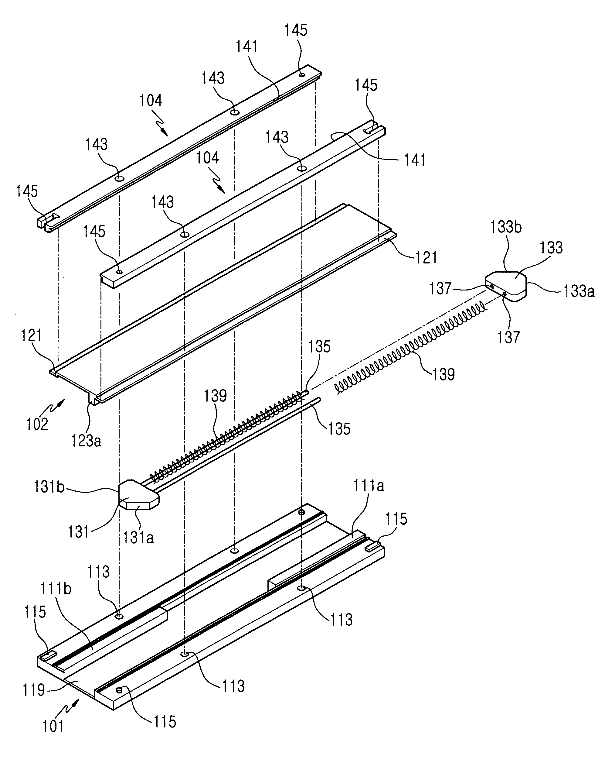
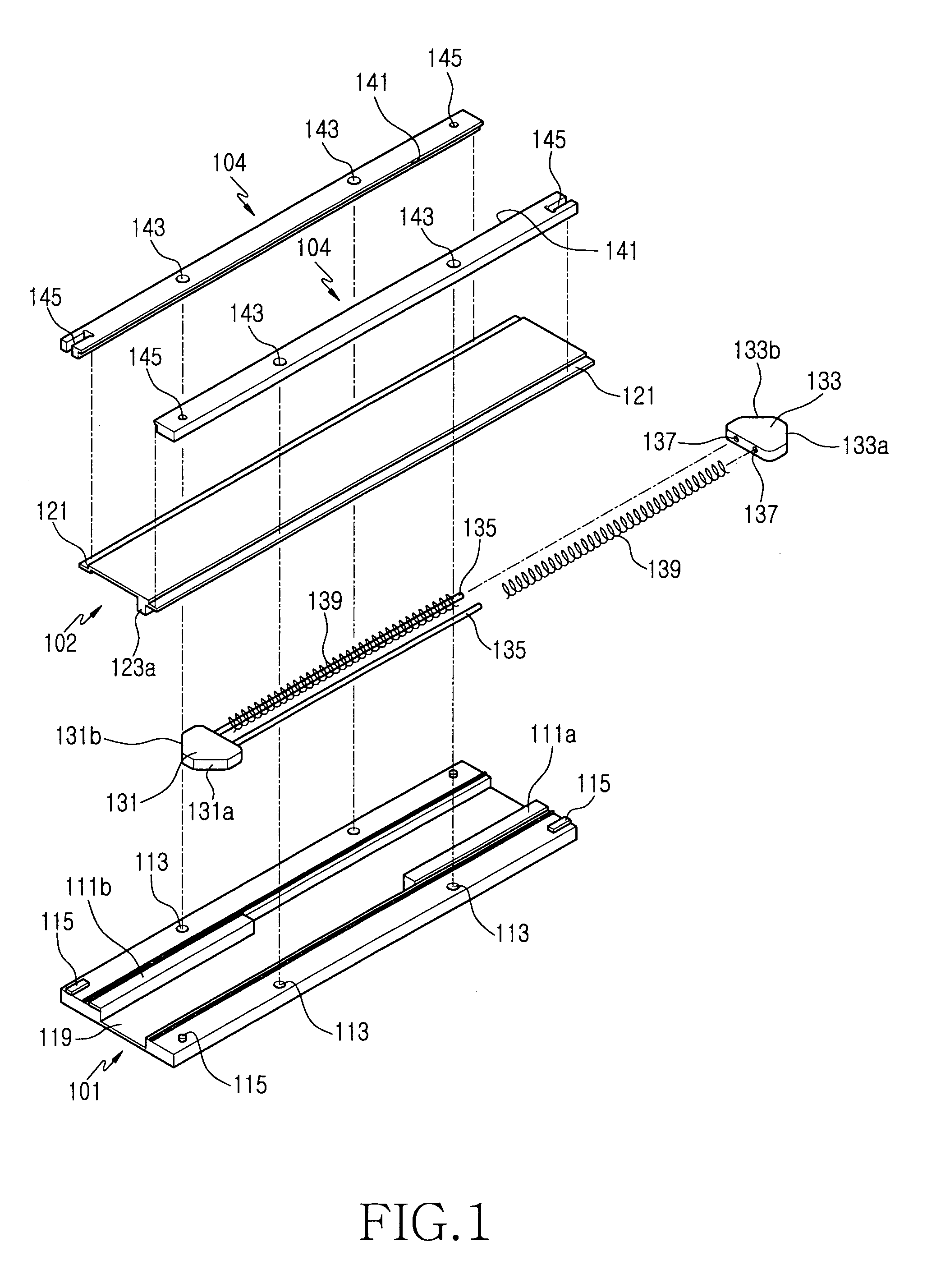
[0057]The sliding guide 101 of the sliding module 100 is mounted on the front of the first housing 201, and the sliding plate 102 is mounted on the rear of the second housing 202.

[0058]FIG. 6 shows a state in which the second housing 202 has covered the keypad 211 and the transceiver unit 213. In this state, the sliding module 100 is positioned as shown in FIG. 3. When a user moves the second housing 202 upward, it gradually slides along the top of the first housing 201.

[0059]FIG. 7 shows a state in which t...

second embodiment

[0064]FIGS. 9 and 10 are front views showing a portable terminal 300 having the sliding module 100. The portable terminal 300 includes a first housing 301 having a display unit 311 and a receiver unit 313, and a second housing 302 having a keypad 321 and a transceiver unit 323. The second housing 302 is coupled with the first housing 301 such that the second housing 302 encloses at least three sides of the first housing 301 including front surface and two opposite sides, and is adapted to expose and cover the display unit 311 by the sliding motions of the second housing 302 against the first housing 301.

[0065]The sliding guide 101 of the sliding module 100 is mounted on the inner opposite sides of the second housing 302, and the sliding plate 102 is mounted on opposite sides of the first housing 301 in order to couple the first housing 301 with the second housing 302 in a manner such that they can slide.

[0066]In contrast to the first embodiment of the portable terminal 200, the seco...


PUM


Abstract

A sliding module employing a semi-automatic opening / closing of the portable terminal, is disclosed. A driving force is used to open and close the sliding-type portable terminal with the resilient force of an elastic means, by converting the direction of the driving force by means of sliders formed on a sliding guide and a sliding plate, respectively. Thus, a user can conveniently manipulate the sliding-type portable terminal.

Description

PRIORITY[0001]This application claims priority to an application entitled “Sliding Module For Portable Terminal” filed in the Korean Industrial Property Office on Mar. 14, 2005 and assigned Serial No. 2005-21054, the contents of which are incorporated herein by reference.BACKGROUND OF THE INVENTION[0002]1. Field of the Invention[0003]The present invention relates to a portable terminal, and more particularly to a sliding module for a sliding-type portable terminal, wherein a pair of housings are coupled in a manner such that they can slide in a longitudinal direction in order to open or close in a sliding motion.[0004]2. Description of the Related Art[0005]In general, current conventional portable terminals may be classified into various types according to their appearance, such as bar-type portable terminals, flip-type portable terminals and folder-type portable terminals.[0006]The bar-type portable terminal has a single main housing, which is provided with a data input / output devi...

Claims


Application Information

Patent Timeline
Patent Type & Authority Patents(United States)
IPC IPC(8): H02G3/04
CPCH04M1/0237A61B5/202A61B5/227A61B5/4337A61B5/4519A61B5/486A61B5/7405A61H19/44A61N2/00A63B21/00196A63B21/0087A63B23/20A63B24/00A63B71/0622A61H2201/0235A61H2201/025A61H2201/10A61H2201/5007A61H2201/5048A61N2005/066A63B2213/007A63B2220/51A63B2225/62A63B2225/64
Inventor PARK, JOSEPH JUSEOP
Owner SAMSUNG ELECTRONICS CO LTD
Why Eureka
Try Eureka