High resolution atom probe

a technology of atom probes and atom probes, applied in the field of atom probe microscopy, can solve the problems of limited ability to accurately identify ions, uncertainty or errors in compositional analysis provided, and limit the ability of atom probes to distinguish between ions of nearly similar masses, so as to effectively serve as a single electrode, the effect of assisting image data quality

Active Publication Date: 2007-01-02
CAMECA INSTR
View PDF1 Cites 15 Cited by
  • Summary
  • Abstract
  • Description
  • Claims
  • Application Information

AI Technical Summary

Benefits of technology

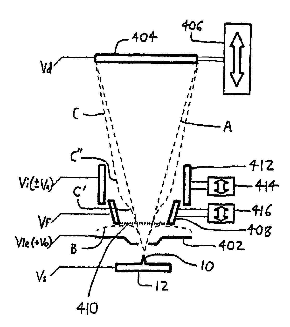
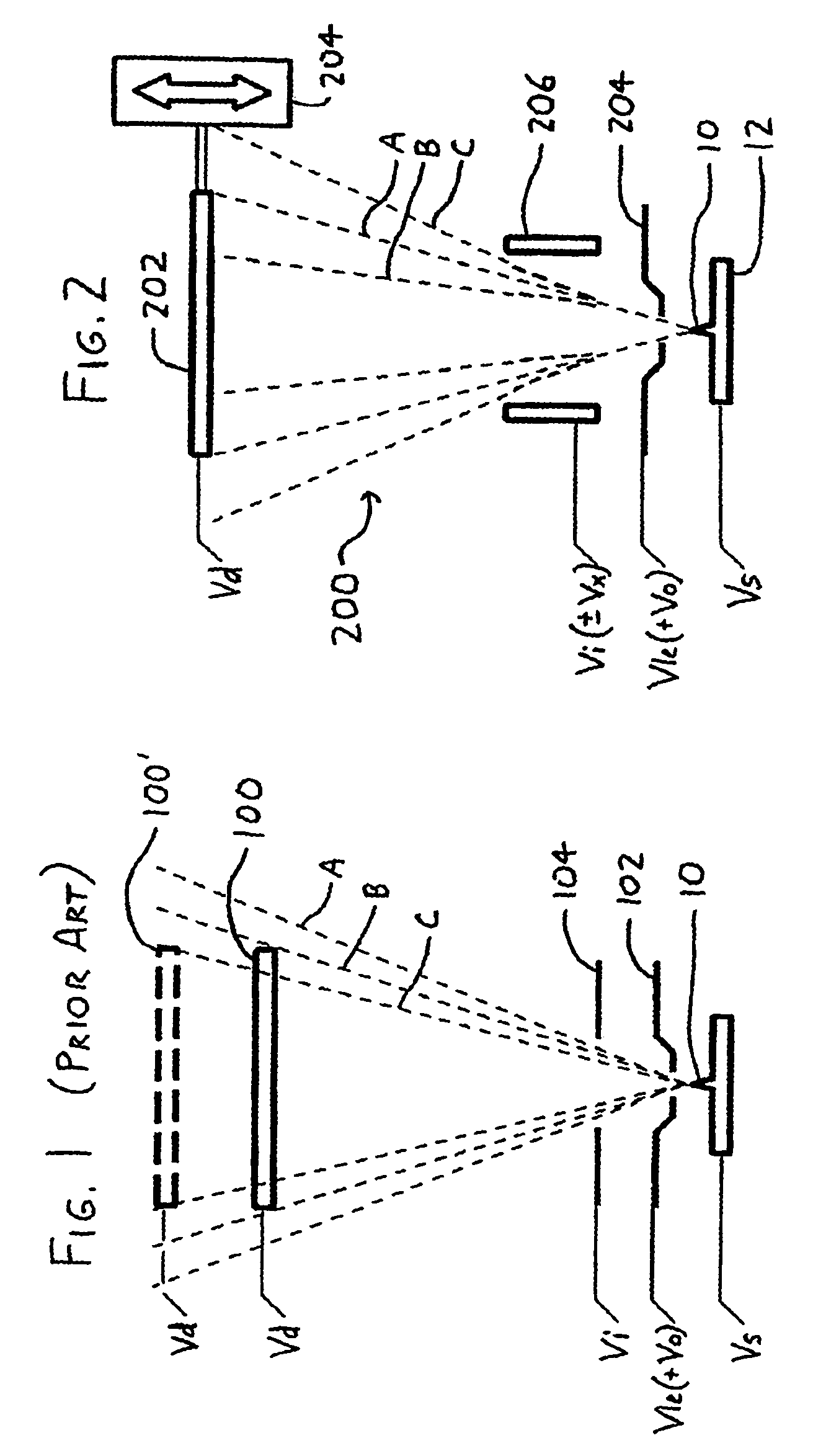
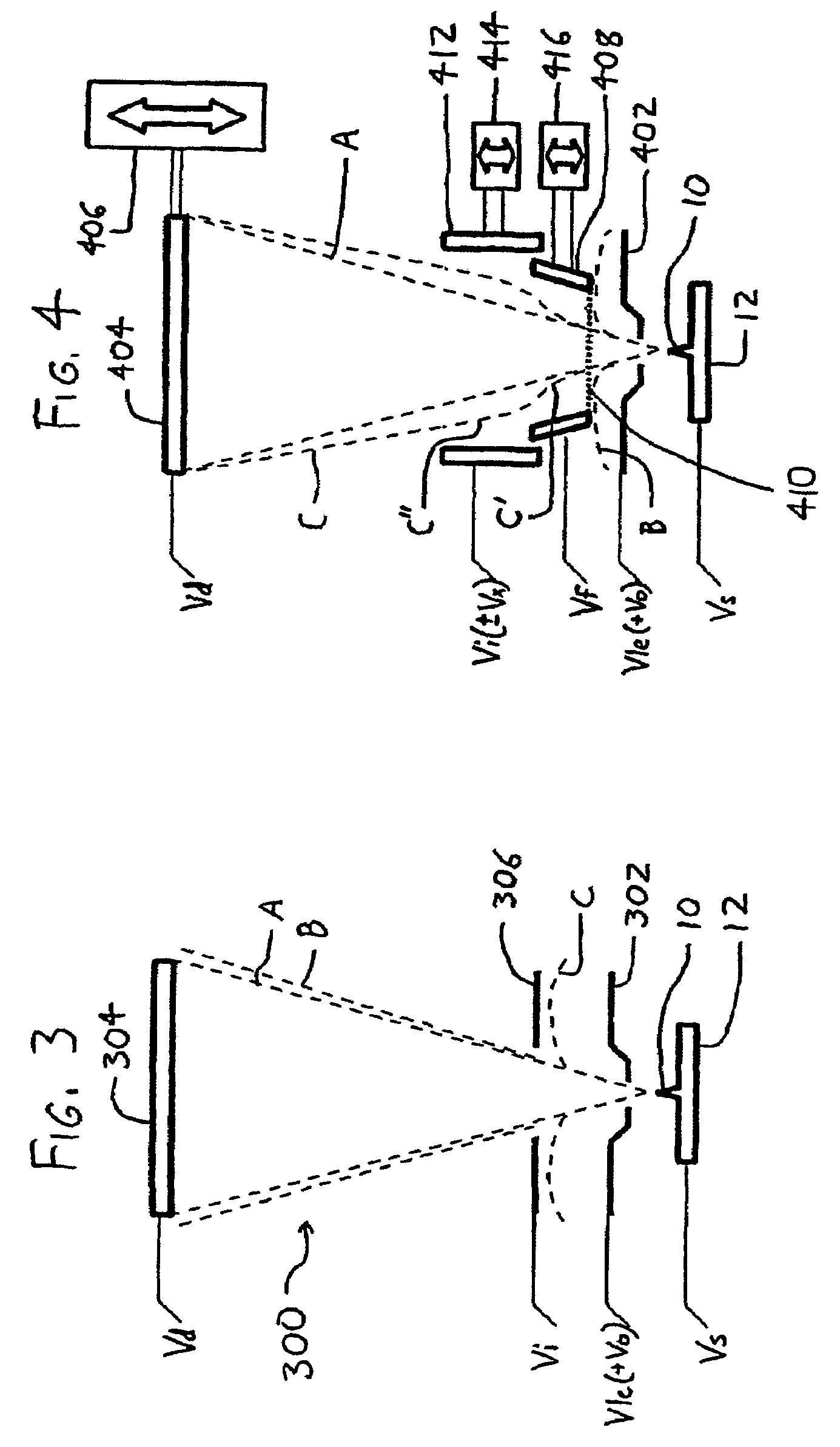
[0014]An intermediate electrode is then situated between the local electrode and the detector along the ion flight path between the specimen mount and the detector. This intermediate electrode may serve as a focusing electrode which assists in adjusting field of view and magnification, and / or as a filtering electrode which helps eliminate spurious ions and thereby assists in image data quality. When the intermediate electrode serves as a focusing electrode (as depicted by the focusing electrode 206 in FIG. 2 and the focusing electrode 412 in FIG. 4), its potential is adjusted about the potential of the local electrode (preferably to a potential between that of the local electrode and the detector), whereby the flight path of ions traveling adjacent the first intermediate electrode and between the local electrode and the detector may be adjusted; for example, with reference to FIG. 2, the flight cone may be adjusted from A to the narrower flight cone B, or to the wider flight cone C). As exemplified by the focusing intermediate electrode 412 in FIG. 4, the focusing electrode is preferably also repositionable along the ion flight path between the specimen mount and the detector, and it preferably has a tubular configuration with an interior length oriented along the ion flight path between the specimen mount and the detector, whereby ions traveling from any specimen on the specimen mount to the detector travel through the interior length of the intermediate electrode.
[0016]A particularly preferred arrangement is as depicted in FIG. 4, wherein at least two intermediate electrodes are provided between the local electrode and the detector, wherein at least one serves as a filtering electrode and at least one serves as a focusing electrode. As exemplified in FIG. 4, a focusing intermediate electrode 412 may be provided between a filtering intermediate electrode 408 and the detector 404, wherein the focusing intermediate electrode 412 is charged to a potential between that of the filtering electrode 408 and the detector 404. The intermediate electrodes may be formed in such a manner that one may be received within the interior of the other, and by making either or both of the electrodes movable along the flight path, the relative positions of the electrodes can be readily adapted to provide a variety of focusing and filtering effects (and if desired, the electrodes can be interfit and can cooperate to effectively serve as a single electrode).

Problems solved by technology

One performance limitation of atom probes is their ability to distinguish between ions of nearly similar masses.
This property, known as mass resolution, limits the ability to accurately identify ions from the specimen, and leads to uncertainty or errors in the compositional analysis provided by atom probes.
Mass resolution limitations are a consequence of the probabilistic nature of ionization: the precise moment at which ionization occurs during an overvoltage pulse Vo can vary slightly between pulses, and thus there are limitations in precisely determining the time of evaporation.
Additionally, owing to practical limitations and expense, pulsing systems for applying the overvoltage pulse Vo tend to apply a pulse wherein the amplitude of Vo is not constant over the duration of the pulse, and thus the exact escape potential (and thus velocity and time of flight) of an evaporated ion will vary.
While these limitations are expected to diminish as the available pulsing electronics grow in quality (and decrease in expense), they nonetheless pose difficulties given the state of the art as of the year 2003.
Another limitation of atom probes relates to the time and expense of testing, particularly in the time and expense of preparing specimens for analysis.
However, preparation of specimens—forming their areas of interest at the tips of needles—can be time-consuming and expensive, and can also be difficult where specimens are brittle or otherwise difficult to shape (as is often the case with semiconductor wafer-derived specimens).
To compound the foregoing problems, specimens are often tested only to find that the collected data is incomplete, e.g., the data does not fully represent the regions of the specimen of particular interest.
Data may also be incomplete because a desired feature may rest partially or wholly outside of the field of view of the atom probe, because the ions from the feature had flight paths which did not impinge upon the detector.
It is also possible that data from the desired feature may not be collected at the desired magnification: the detector has a limit to how accurately the location of ion impingement may be measured, and thus insufficient spread in ion flight paths may tax the sensitivity of the detector, resulting in “coarse” positional data.
The end result of the foregoing problems is that an experimenter may undergo the time-consuming steps of specimen preparation, atom probe warm-up, and data collection only to find that the data collected has little value: the desired feature is not within the field of view, or has insufficient magnification, or is not sampled to the desired depth, etc.
This is particularly problematic where the specimen(s) are rare, expensive, or one-of-a-kind: there may not be a second chance to obtain the desired data.

Method used


Image

  • High resolution atom probe
  • High resolution atom probe
  • High resolution atom probe

Examples


Embodiment Construction

[0022]Referring to FIG. 2, an atom probe exemplifying certain preferred features of the invention is designated generally by the reference numeral 200. A specimen 10 is situated on a specimen mount 12, which is charged to a datum potential Vs. A detector 202 is spaced from the specimen 10, and as in prior arrangements, an attractive potential gradient is maintained between the specimen 10, a local electrode 204, and the detector 202: surface atoms on the specimen 10 are ionized by the electric field at the specimen surface as a result of the momentarily applied potential (equal to Vs−(Vle+Vo)), and accelerated towards the local electrode 204 and the detector 202.

[0023]The detector 202 is situated on a positioning stage 204 which allows the detector 202 to be repositioned at least along the axis of the flight cone A wherein evaporated ions travel from the specimen 10 when overvoltage pulses Vo are applied to the local electrode 204. Such a positioning stage 204 may take the form of v...


PUM

PropertyMeasurementUnit
positive voltageaaaaaaaaaa
diameteraaaaaaaaaa

Abstract

A three dimensional atom probe comprising a sharp specimen (10) coupled to a mounting means (12) where emission of charged particles is caused by application of a potential to the specimen tip (10) such that charged particles are influenced by filtering electrodes (206, 204) before impingement on a detection screen (202).

Description

CROSS-REFERENCE TO RELATED APPLICATIONS[0001]This appiication is a U.S. national phase application of PCT / US2004 / 016590, filed May 26, 2004, which claims the benefit of U.S. Provisional Patent Application Ser. No. 60 / 476,348, entitled “HIGH RESOLUTION ATOM PROBE,” filed Jun. 6, 2003, which is incorporated herein in its entirety by reference.FIELD OF THE INVENTION[0002]This document concerns an invention relating generally to the field of atom probe microscopy.BACKGROUND OF THE INVENTION[0003]The three-dimensional atom probe (3DAP), also known as a position-sensitive atom probe (POSAP), is a device which allows specimens to be analyzed on an atomic level. Typical atom probes operate by (usually positively) ionizing and extracting atoms from a specimen's surface. FIG. 1 presents a schematic view of an exemplary atom probe of a more recent type, wherein the locations and identities of the component atoms of a specimen 10 are determined by situating the specimen 10 opposite a position-s...

Claims


Application Information

Patent Timeline
Patent Type & Authority Patents(United States)
IPC IPC(8): G21K7/00G21K5/08G21K5/10G01NG01N25/00H01J37/285
CPCB82Y15/00H01J37/05H01J37/10H01J37/285H01J2237/244H01J2237/024H01J2237/0492H01J2237/053
Inventor GRIBB, TYE TRAVIS
Owner CAMECA INSTR
Why Eureka
Try Eureka