Switch cabinet for a tablet press

a tablet press and switch cabinet technology, applied in the direction of press ram, heating type, lighting and heating apparatus, etc., can solve the problems of reducing the operating range of the entire unit, contaminated filter and air conditioner parts, and difficult and costly cleaning of contaminated parts, so as to reduce heat transfer resistance and reduce the air speed thereon , the effect of reducing the thermal resistan

Active Publication Date: 2007-01-02
FETTE
View PDF19 Cites 10 Cited by
  • Summary
  • Abstract
  • Description
  • Claims
  • Application Information

AI Technical Summary

Benefits of technology

[0009]The disclosed hood is pivotally mounted about a vertical axis on the switch cabinet housing or on the lower housing part, so that access to the interior of the housing can be easily obtained and it is possible to clean parts of the switch cabinet, in particular the heat sinks.
[0011]The heat transfer according to the invention substantially takes place via two heat transfer resistors. The heat is transferred from the internal air in the interior of the switch cabinet housing to its thermally conductive walls and from there to the outside air in the ventilation duct. Naturally the heat transfer resistance is reduced on a surface when the air speed thereon is increased. By enlarging the heat emission surface the thermal resistance can also be reduced. Thus it is advantageous when the ventilation duct covers as large a part as possible of the walls of the switch cabinet housing.

Problems solved by technology

The heating naturally restricts the operating range of the entire unit.
With the disclosed preventative measures there is the danger that the filter and air conditioners become contaminated.
Cleaning the contaminated parts proves to be difficult and costly.

Method used


Image

  • Switch cabinet for a tablet press
  • Switch cabinet for a tablet press

Examples


Embodiment Construction

[0014]While this invention may be embodied in many different forms, there are described in detail herein a specific preferred embodiment of the invention. This description is an exemplification of the principles of the invention and is not intended to limit the invention to the particular embodiment illustrated

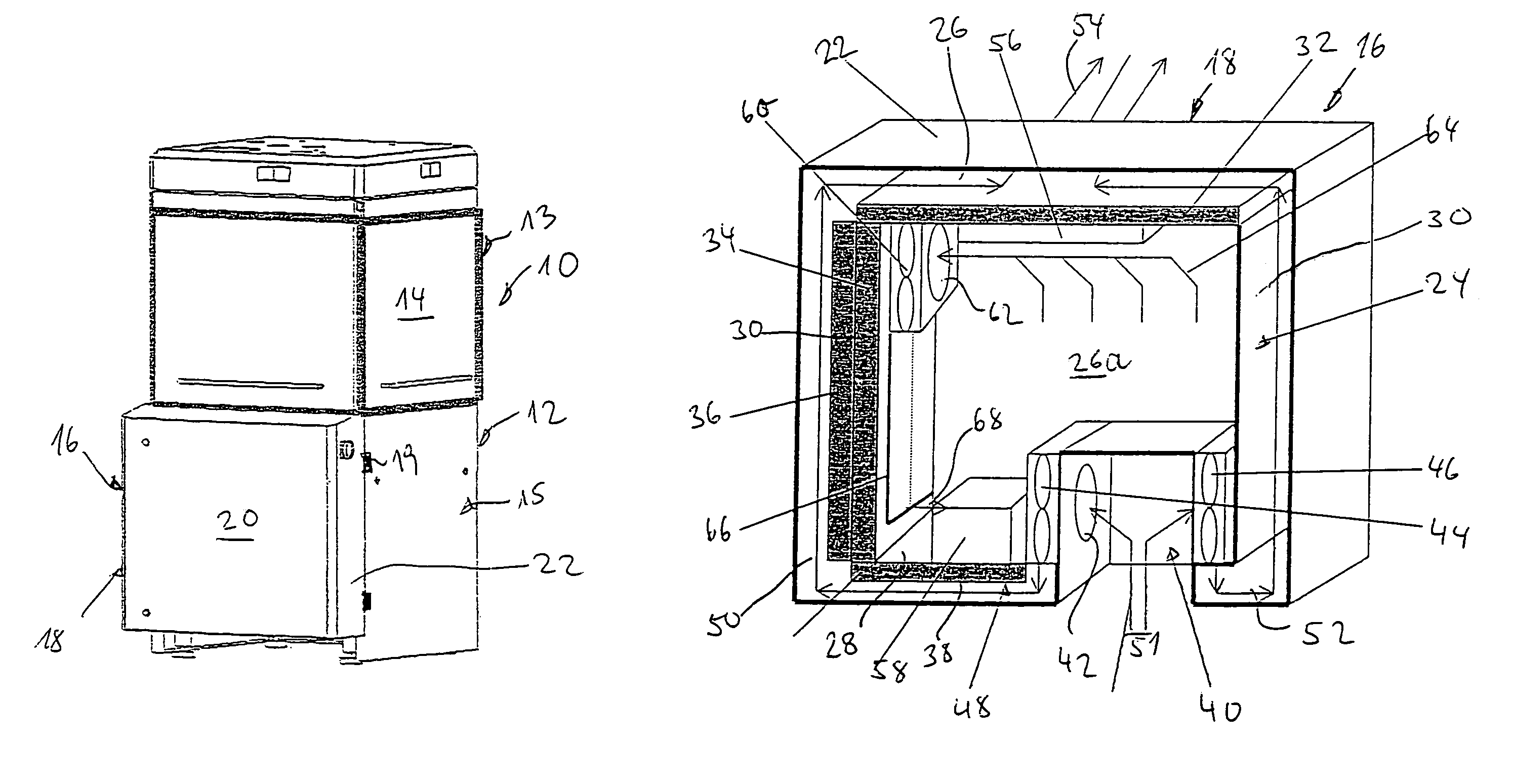
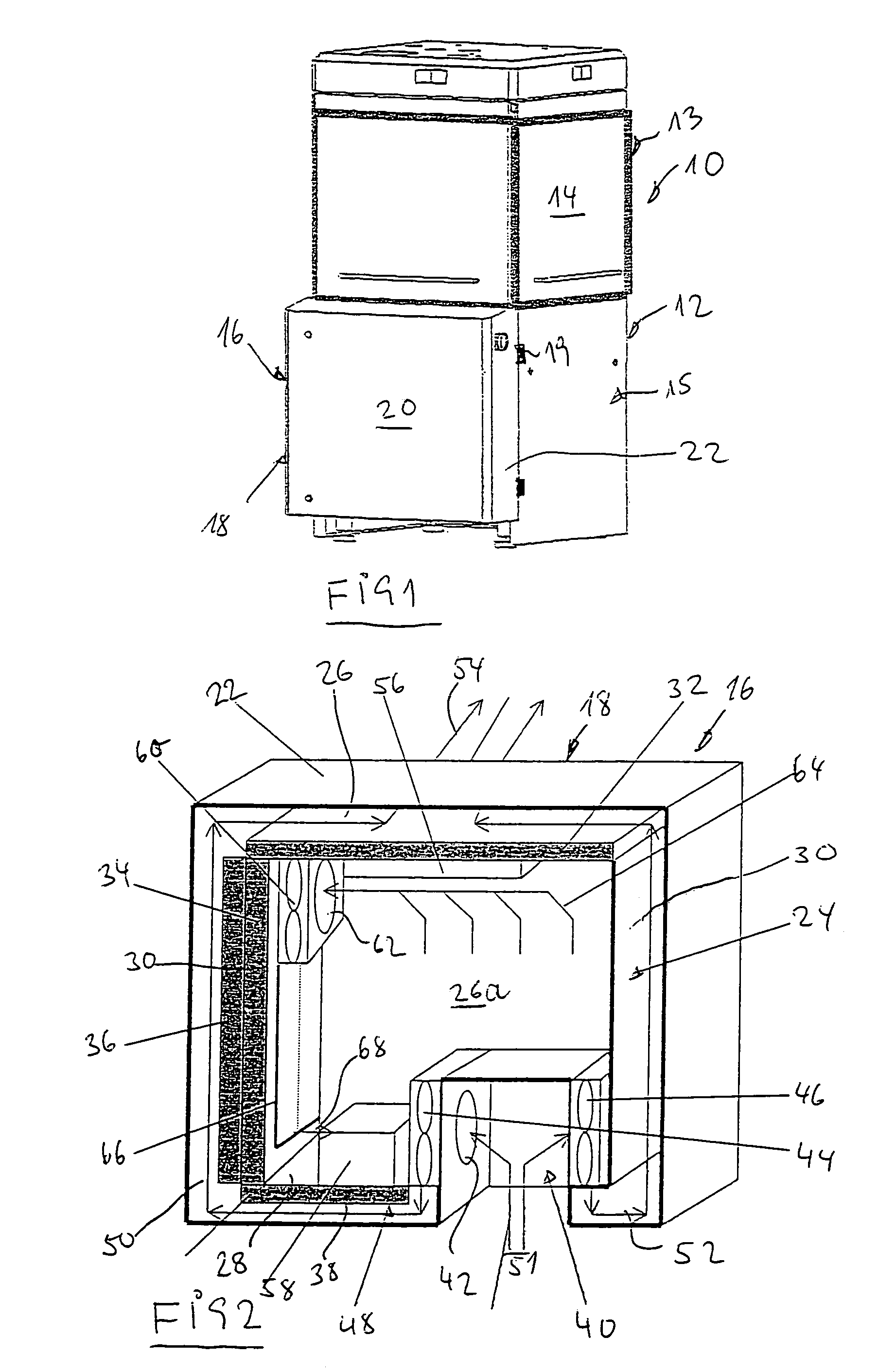
[0015]FIG. 1 is a perspective view of a tablet press according to the invention with a switch cabinet attached to the front.

[0016]FIG. 2 shows the switch cabinet according to FIG. 1 with the front wall removed.

[0017]In FIG. 1 a rotary tablet press (10) is shown diagrammatically. It comprises a housing (12) with an upper housing part (13), the walls thereof being transparent in the upper region at (14), and a lower housing part (15). The housing part (13) houses conventional parts of a rotary press, such as a rotor, pressing tools etc and the lower housing part contains, for example drives for the rotor, peripheral apparatus etc. The individual parts are however not to be descr...


PUM


Abstract

Tablet press, with an upper housing part for receiving a rotor and comprising pressing tools, a lower housing part with side walls for receiving a drive device for the rotor, servo drives for peripheral apparatus for the tablet press, a switch cabinet for receiving a machine computer, electrical parts, components, such as power units with their control switches for the drive device, servo drive and peripheral apparatus, a switch cabinet housing with a rear wall, a bottom wall, a cover wall and side walls and an open front face being attached via its rear face to the outer face of a side wall of the lower housing part, furthermore with a hood which comprises hood side walls and a hood cover wall and which is pivotally mounted about a vertical axis on the switch cabinet housing or on the lower housing part by means of a hood side wall, the hood being constructed and slidable over the switch cabinet housing, in such a manner that the hood cover wall seals the front face of the switch cabinet housing and the hood side walls comprise a spacing with all the walls of the switch cabinet housing to form a ventilation duct almost completely surrounding the switch cabinet housing, furthermore with a first fan which feeds outside air into the ventilation duct via at least one inlet aperture in the hood, an outlet aperture in the hood via which the air escapes out of the ventilation duct and a second fan which circulates air in the interior of the switch cabinet housing in such a manner that it spreads along the inner face of the switch cabinet walls.

Description

CROSS-REFERENCE TO RELATED APPLICATIONS[0001]Not applicable.STATEMENT REGARDING FEDERALLY SPONSORED RESEARCH[0002]Not applicable.BACKGROUND OF THE INVENTION[0003]In addition to conventional rotary presses, tablet manufacturing units include further parts and peripheral apparatus. The substantial electrical and electronic components and parts for the control and regulation of the main drive of the press and the servo drive in the press and in peripheral apparatus are combined in a switch cabinet which in conventional presses is connected to the tablet press via a cable. Further parts of the unit are, as mentioned above, peripheral apparatus, such as for example dust removal devices, testing devices etc. which are connected to the switch cabinet via a terminal block of the tablet press.[0004]The electrical components in the switch cabinet, in particular the machine computer and the power units, heat up during operation and it is necessary to provide sufficient cooling to restrict the ...

Claims


Application Information

Patent Timeline
Patent Type & Authority Patents(United States)
IPC IPC(8): H05K7/20F24F7/007B30B1/04
CPCB30B11/08H05K7/206B30B15/148
Inventor HINZPETER, JURGENSCHMIDT, INGOSEIFERT, WERNEROLDENBERG, ALEXANDER
Owner FETTE
Why Eureka
Try Eureka