Feedback scheme for video compression system

Inactive Publication Date: 2007-01-02
CIRRUS LOGIC INC
View PDF61 Cites 96 Cited by
  • Summary
  • Abstract
  • Description
  • Claims
  • Application Information

AI Technical Summary

Problems solved by technology

Further, the difference data may include inter-frame image differences

Method used


Image

  • Feedback scheme for video compression system
  • Feedback scheme for video compression system
  • Feedback scheme for video compression system

Examples


Embodiment Construction

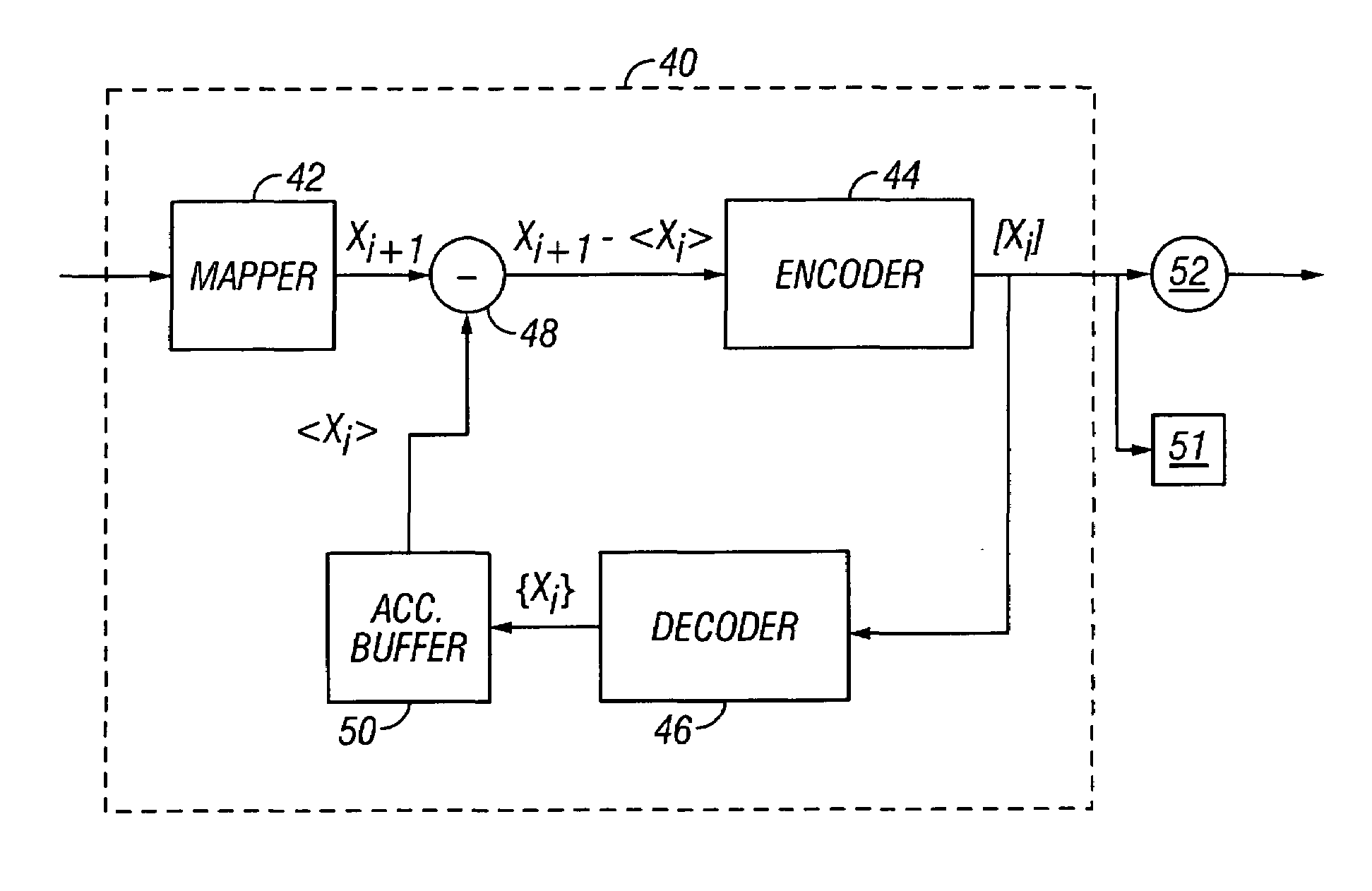
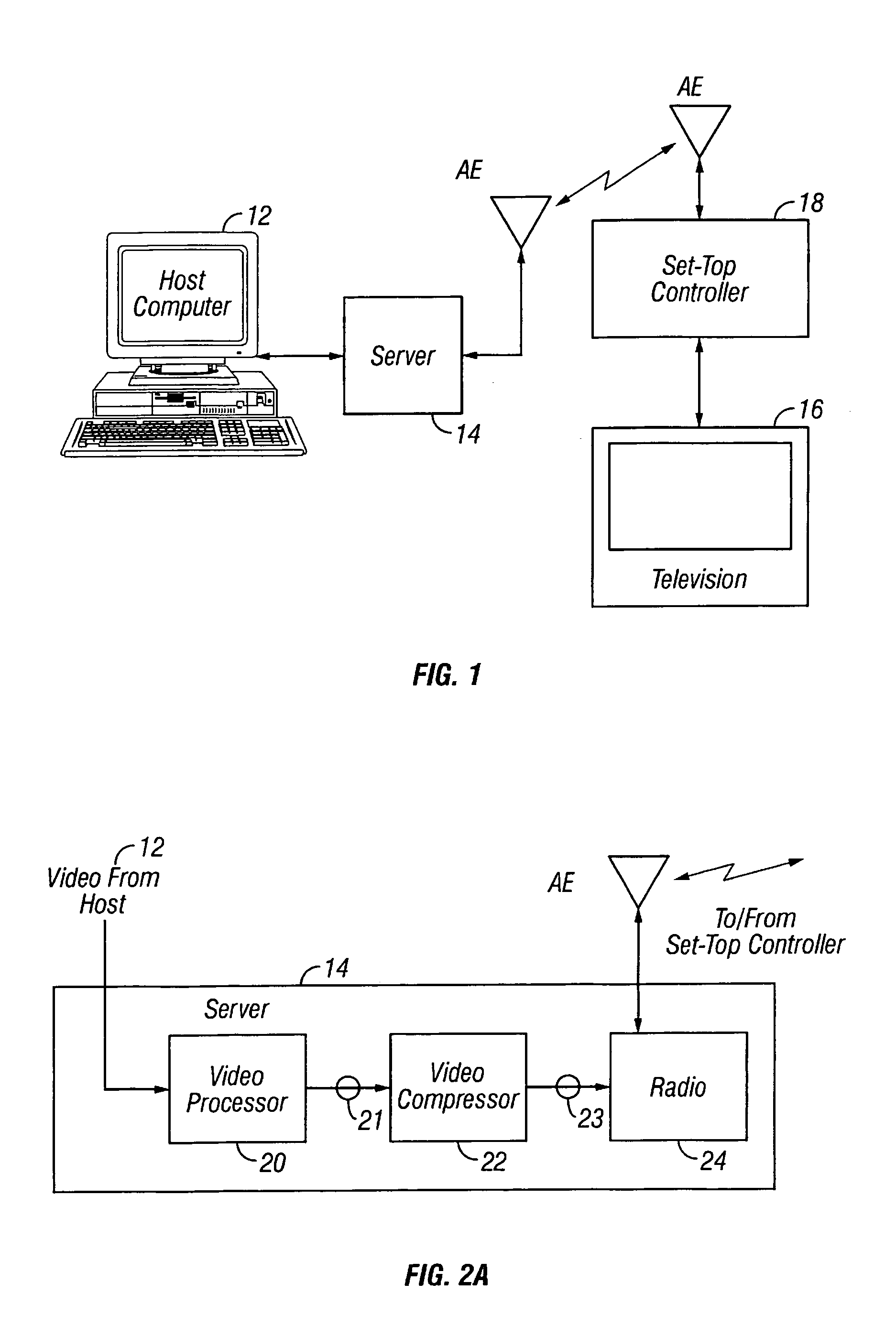
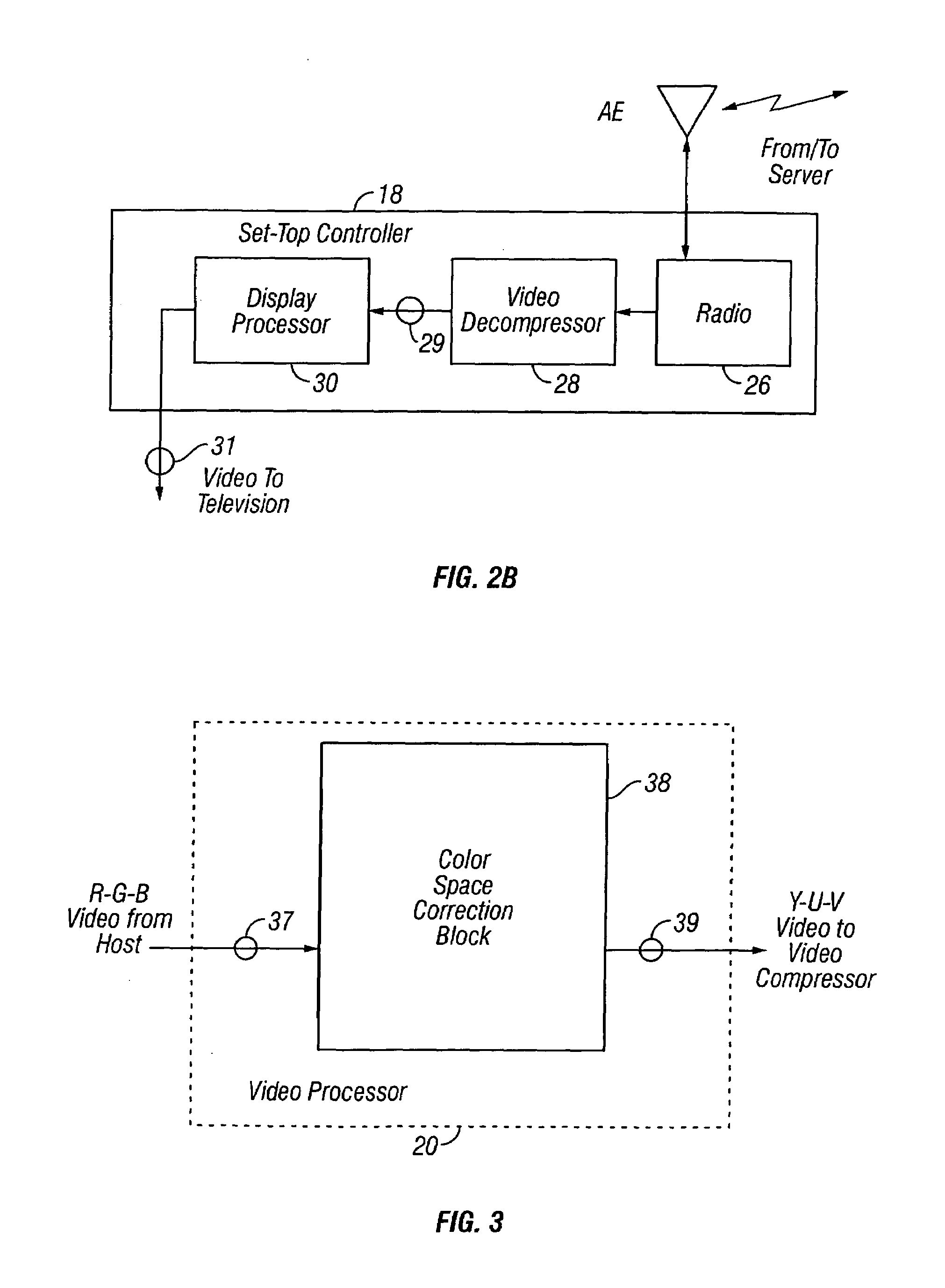
[0037]A video processing scheme that may find application in a digital wireless home network or other computer network environments is disclosed herein. The video processing scheme includes an adaptive feedback mechanism, which operates as follows. While transmitting a “compressed” (e.g., a wavelet transformed / quantized / entropy encoded) video frame, it is decompressed and stored as a reference for a next frame. When the next frame arrives, the stored frame is subtracted from it, and the resulting difference (i.e., between the new frame and what has been transmitted so far) is compressed and ultimately transmitted. For an exemplary compression scheme, this difference is expected contain at least an order of magnitude less energy than the previous frame, therefore lending itself to much easier compression (higher compression ratio at less distortion). On the receiver side, the new (i.e., difference) frame will be added to the previous one, thus contributing to building up the resoluti...


PUM


Abstract

The quality of digital images recovered from compressed data in an inter-frame redundancy-removing scheme is enhanced using a self-adaptive feedback scheme in an image compression/decompression system so as to provide for the compensation of the distortion component from prior frame compression in subsequent difference frame compression. Each transmitted frame is stored after a full compress/decompress cycle, and difference data (which includes the inverse of the distortion component from compression of the transmitted frame) representing the difference between the stored frame and the incoming new frame is transmitted. Consequently, the quality of static regions in the recovered images may be improved with each subsequent iteration by taking the distortion component in the prior frame into consideration along with the inter-frame motion information. The feedback loop thus forms a self-adaptive iterative cycle.

Description

RELATED APPLICATION[0001]This application is a continuation of Ser. No. 09 / 178,284 filed on Oct. 23, 1998 now abandoned entitled “Inter / Intra Frame Deciding in Image Compression” by inventor Persiantsev, which is a continuation in part of Application Ser. No. 09 / 164,942, entitled “Method and Apparatus for Digital Data Compression”, filed Oct. 1, 1998 now abandoned, by Michael I. Persiantsev, Rajugopal R. Gubbi and Joseph d. Harwood, incorporated herein by reference in its entirety.FIELD OF THE INVENTION[0002]The present invention relates to digital data compression, and in particular to a scheme for temporal coherent image data compression, and more particularly to a self-adaptive compression scheme for motion digital video compression.BACKGROUND[0003]With the convergence of digital information in the home, a need has arisen for the integration of home computers with other information appliances. In co-pending application Ser. Nos. 08 / 792,003 and 08 / 792,361, both filed Jan. 31, 1997...

Claims


Application Information

Patent Timeline
IPC IPC(8): G06K9/36G06K9/46H04N7/26
CPCH04N19/63H04N19/90H04N19/192
Inventor PERSIANTSEV, MICHAEL I.
Owner CIRRUS LOGIC INC
Why Eureka
Try Eureka