
Cache operation with non-cache memory

a non-cache memory and cache technology, applied in the field of memory systems, can solve problems such as invalidating the whole cache memory

Active Publication Date: 2007-01-02
MALIKIE INNOVATIONS LTD
View PDF11 Cites 33 Cited by
  • Summary
  • Abstract
  • Description
  • Claims
  • Application Information

AI Technical Summary

Problems solved by technology

Also, in some systems the whole cache memory is invalidated when part of the non-fast read-write memory is being programmed.

Method used


Image

  • Cache operation with non-cache memory
  • Cache operation with non-cache memory
  • Cache operation with non-cache memory

Examples


Embodiment Construction

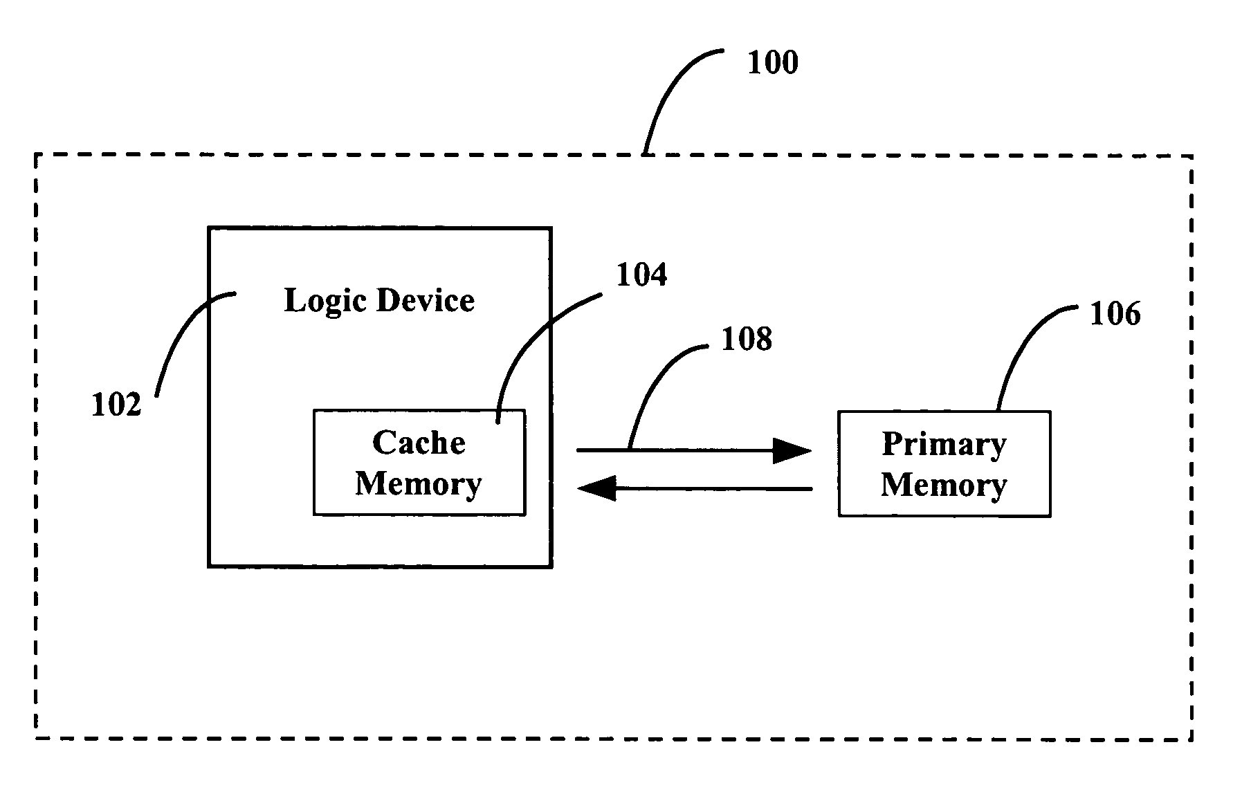
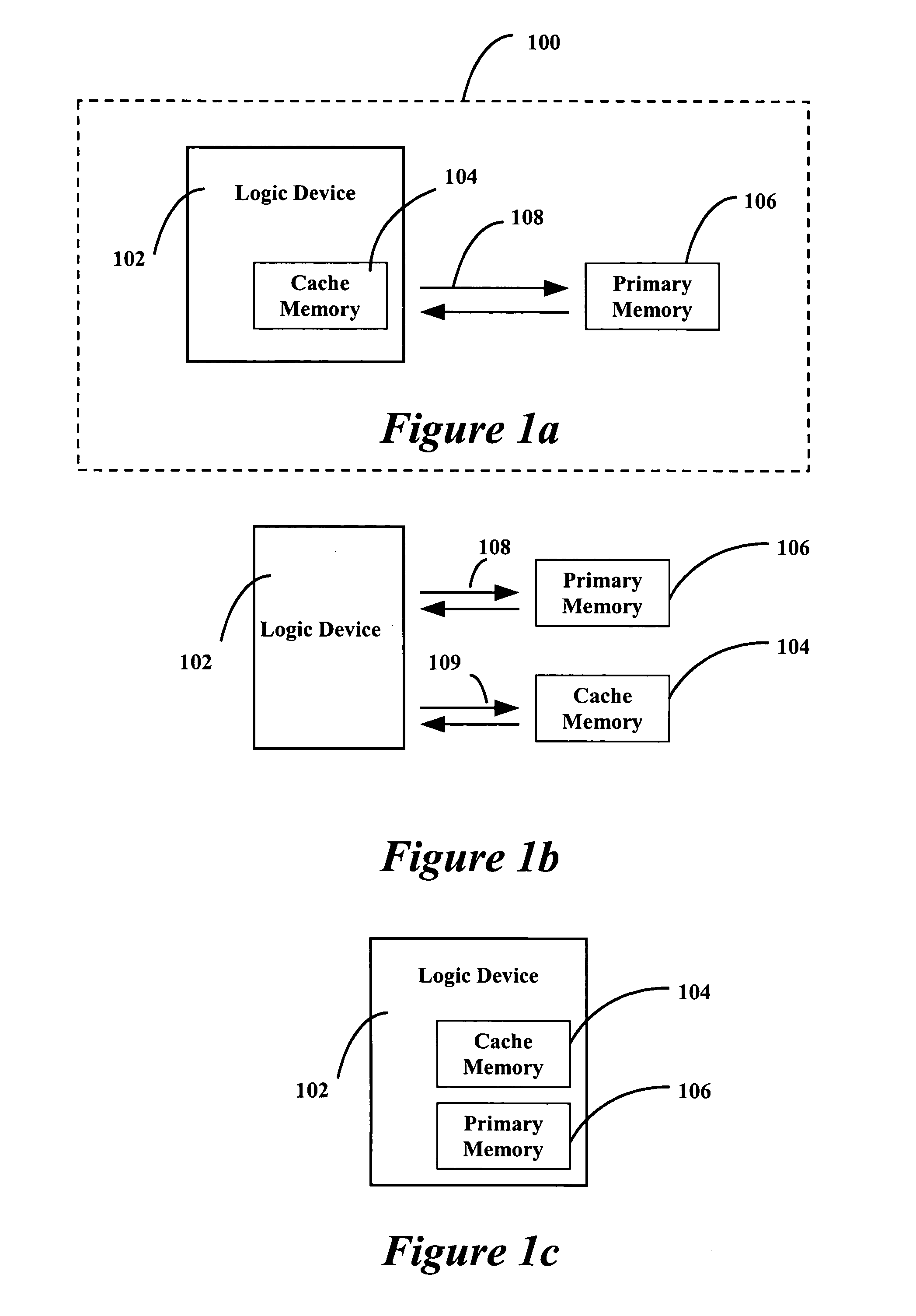
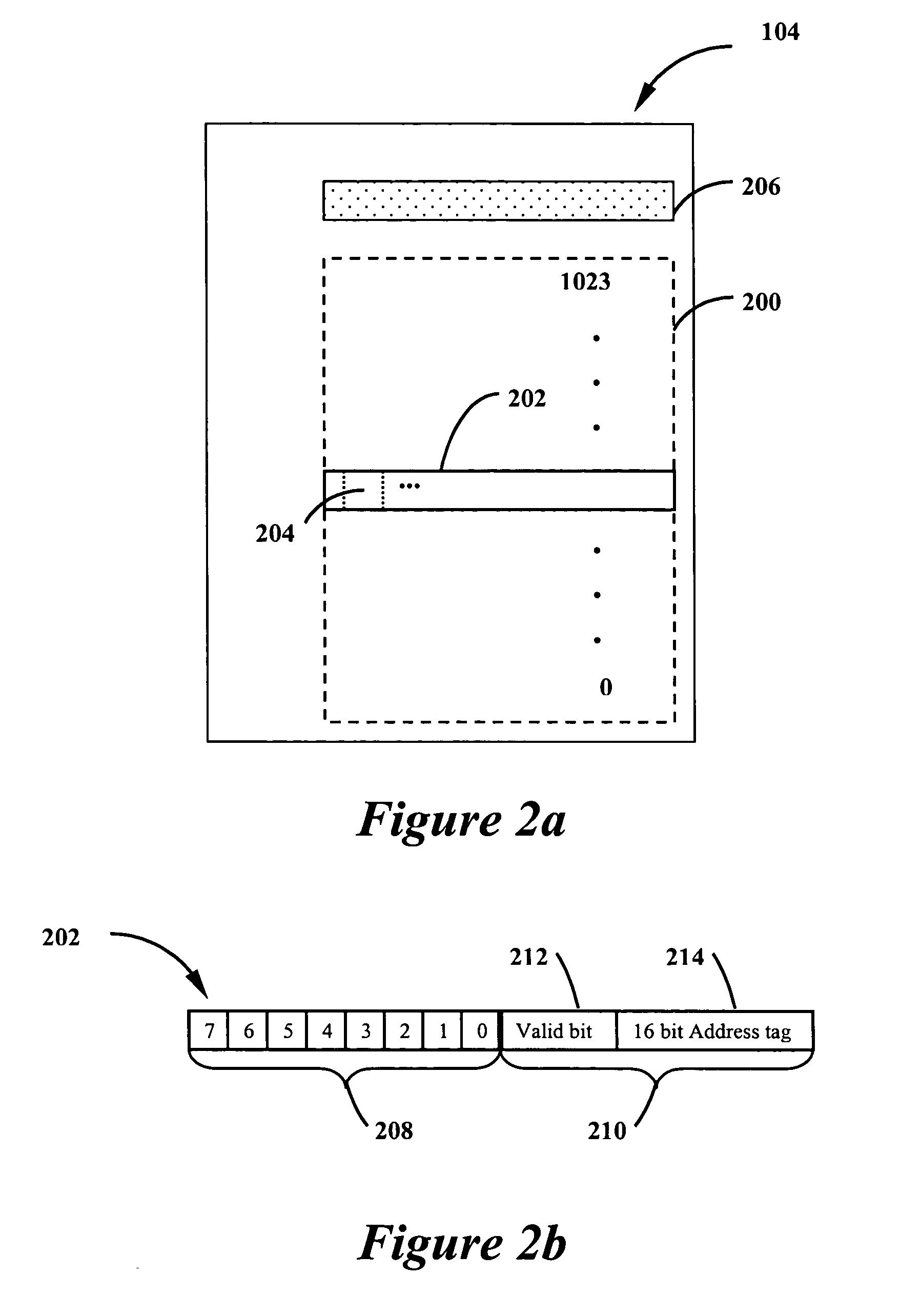
[0021]Shown in FIG. 1a is an exemplary configuration of electronic or computer system 100 that has both primary and cache memory subsystems. The exemplary system 100 comprises a logic subsystem 102, a cache memory subsystem 104 and a primary memory subsystem 106. The logic subsystem may comprise one or more logic devices including, but not limited to a microprocessor, micro-controller, programmable logic device, and others. In the exemplary system shown, the cache memory subsystem 104 physically resides in the logic subsystem 102, and the cache memory subsystem 104 and the logic subsystem 102 are coupled together such that they are in communication with each other. Shown in FIG. 1a is a single cache memory system 104, but the system 100 could include multiple cache memory subsystems. The primary memory subsystem 106 is connected to and communicates with the logic device subsystem 102 via a primary memory communications link 108. The primary memory communications link 108 provides a ...


PUM


Abstract

A system and method are provided for bypassing cache memory when reading data from system memory particularly when the primary memory could include memory types where the read operation mixes non-data with data. A system and method are provided for bypassing and invalidating cache memory when writing data to system memory particularly when the primary memory could include memory types where the write operation mixes non-data with data.

Description

CROSS-REFERENCE TO RELATED APPLICATIONS[0001]This application claims the benefit of U.S. Provisional Application No. 60 / 482,180 entitled “Cache Operation With Flash Memory,” which was filed on Jun. 24, 2003. The entire disclosure of U.S. Provisional Application No. 60 / 482,180 is hereby incorporated into the present application by reference.BACKGROUND[0002]1. Field[0003]The systems and methods described in this patent document relate generally to memory systems and more specifically to the interaction of logic devices with memory systems that include cache memory.[0004]2. Description of the Related Art[0005]Many electrical or computer systems exist that comprise logic devices, such as micro-processors, micro-controllers, and others, that utilize system memory that comprises both a primary memory subsystem and a cache memory subsystem. Cache subsystems are typically used to decrease the access time for a logic device to acquire information stored in memory. It is desirable for the cac...

Claims


Application Information

Patent Timeline
IPC IPC(8): G06F12/08
CPCG06F12/0888G06F12/0891G06F2212/2022
Inventor MADTER, RICHARD C.
Owner MALIKIE INNOVATIONS LTD
Learn More