Automated process execution for project management

a project management and process execution technology, applied in the field of electronic systems, can solve the problems of too restrictive, insufficient control threads, and insufficient relationship in an automated workflow to minimize the time period

Inactive Publication Date: 2007-01-02
GOOGLE LLC
View PDF51 Cites 106 Cited by
  • Summary
  • Abstract
  • Description
  • Claims
  • Application Information

AI Technical Summary

Problems solved by technology

However, when an attempt is made to automate the development of a software product by applying various mechanisms which are described in the above referenced documents, several major problems are encountered.
However, the above “AND” / “OR” relationships in an automated workflow are not sufficient to minimize the time period that occurs between the start of the strategy phase and start of the production phase in the development of a new software product.
In addition, to implement the relationships among the tasks and phases of a software development project, by only using “threads of control”, is too restrictive.
Here again the use of “threads of control” to try to accomplish all of this is too restrictive.

Method used


Image

  • Automated process execution for project management
  • Automated process execution for project management
  • Automated process execution for project management

Examples


Embodiment Construction

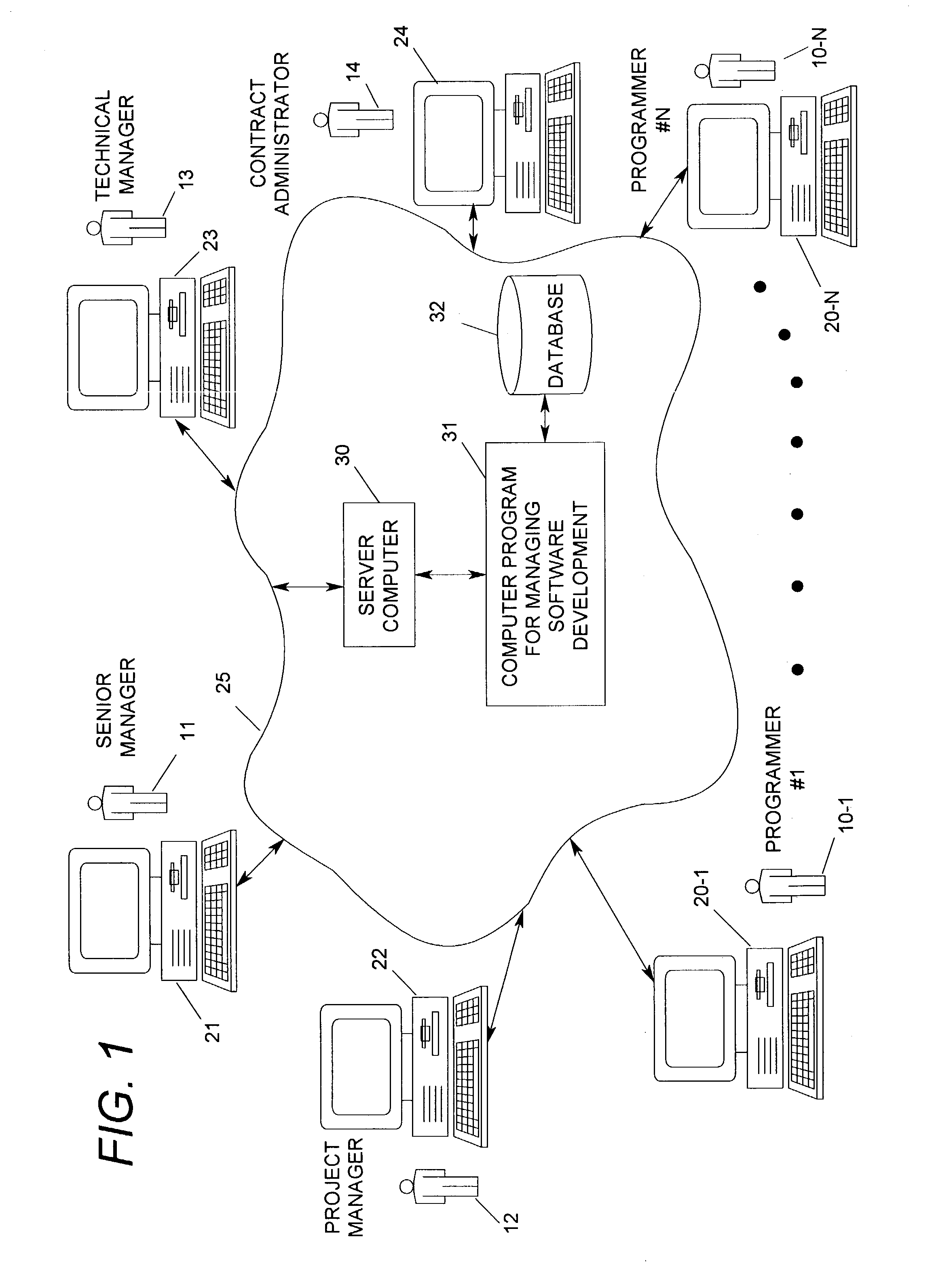
[0029]With reference now to FIG. 1, a system for managing the development of software will be described which constitutes one preferred embodiment of the present invention. The FIG. 1 system is used by a software development team, which consists of a set of programmers 10-1 thru 10-N, a senior manager 11, a project manager 12, a technical manager 13, and a contract administrator 14.

[0030]Included in the FIG. 1 system are a plurality of personal computers which are identified by reference numerals 20-1 thru 20-N, 21, 22, 23 and 24. All of these computers are interconnected by a communications network 25. The personal computers 20-1 thru 20-N are used by the programmers 10-1 thru 10-N respectively; and, the personal computers 21, 22, 23 and 24 are used by the team members 11, 12, 13 and 14 respectively.

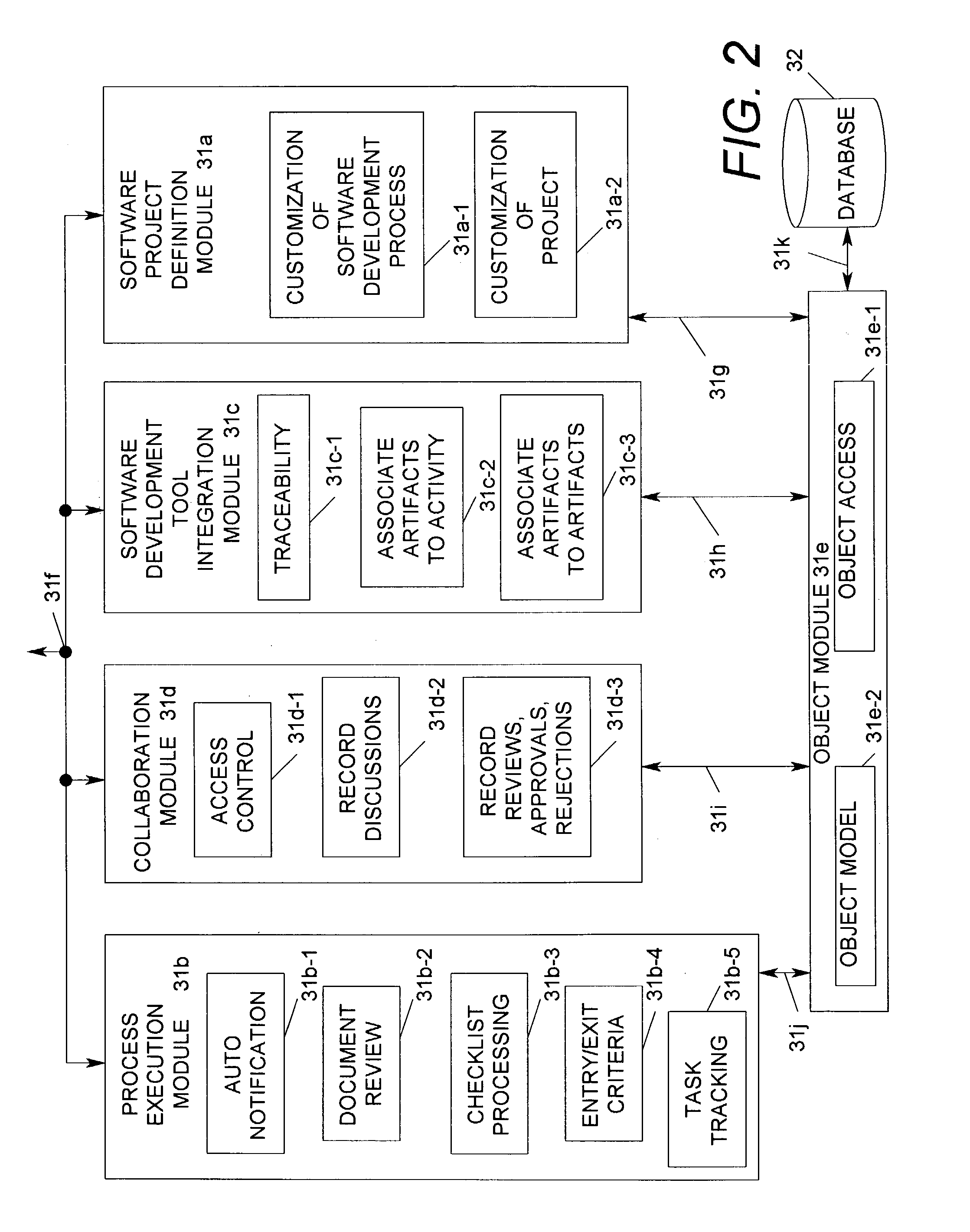
[0031]Also included in the FIG. 1 system is a server computer 30, a computer program 31, and a database 32. The server computer 30 is coupled by the communication network 25 to all of t...


PUM


Abstract

A computer-readable medium causes a computer to operate as a server for managing the development of software by a software development team. Stored on this computer readable medium is a computer program which includes an object module and a process execution module. The object module performs operations on a linked object structure that represents a software development project. The process execution module has one interface that interacts with the object module and has another interface that interacts over a communication network with personal computers of the team members. By this interaction, the phases of each project are started in a non-fixed, non-predictable sequence by—1) sensing when all the tasks, that are represented by an entry set of CRITERIALIST_ITEM objects, are completed, and 2) sending a notice to begin the phase of the project which is related to the one entry set.

Description

RELATED CASES[0001]The invention which is claimed herein is related to two other inventions that are entitled—a) “SERVER COMPUTER PROGRAM HAVING AN OBJECT MODULE AND A SOFTWARE PROJECT DEFINITION MODULE WHICH CUSTOMIZE A LINKED OBJECT STRUCTURE THAT REPRESENTS A SOFTWARE DEVELOPMENT PROJECT” (Ser. No. 10 / 306,604), and b) “SERVER COMPUTER PROGRAM HAVING AN OBJECT MODULE AND A SOFTWARE DEVELOPMENT TOOL INTEGRATION MODULE WHICH INTERLINKS ARTIFACTS IN A SOFTWARE DEVELOPMENT PROJECT” (Ser. No. 10 / 306,602). Patent applications on all of these inventions were filed concurrently on Nov. 26, 2002; and they each have the same Detailed Description, but different sets of claims.BACKGROUND OF THE INVENTION[0002]The present invention relates to electronic systems which are comprised of: a) multiple personal computers, each of which is used by a particular member of a software development team, b) a communication network which couples the personal computers to a server computer, and c) a computer...

Claims


Application Information

Patent Timeline
Patent Type & Authority Patents(United States)
IPC IPC(8): G06F9/44
CPCG06Q10/06G06F8/20
Inventor SADHU, AVINASHKOERBER, PAUL DONALD
Owner GOOGLE LLC
Why Eureka
Try Eureka