Quick change assembly for hydroforming punches

a technology of quick change and assembly, which is applied in the field of hydroforming, can solve the problems of high time-consuming and negative effects on production, and achieve the effects of short time, reduced down time, and improved opening quality

Inactive Publication Date: 2007-01-09
GM GLOBAL TECH OPERATIONS LLC
View PDF6 Cites 31 Cited by
  • Summary
  • Abstract
  • Description
  • Claims
  • Application Information

AI Technical Summary

Benefits of technology

[0007]One advantage of the present invention is that a quick change assembly is provided for a hydroforming punch that allows for quick changing of the punches in the hydroforming die during piercing in an effortless manner and in a very short time while the die is still in the press. Another advantage of the present invention is that the quick change assembly improves quality of an opening created during a hydroforming piercing process due to the ability to change punches as needed. Yet another advantage of the present invention is that the quick change assembly reduces down time during the hydroforming piercing process. Still another advantage of the present invention is that the quick change assembly uses less manpower du

Problems solved by technology

However, the methods currently used to replace a punch in the die, requires the dismount of the hydraulic cylinder and/or the dismount of die

Method used


Image

  • Quick change assembly for hydroforming punches
  • Quick change assembly for hydroforming punches
  • Quick change assembly for hydroforming punches

Examples


Embodiment Construction

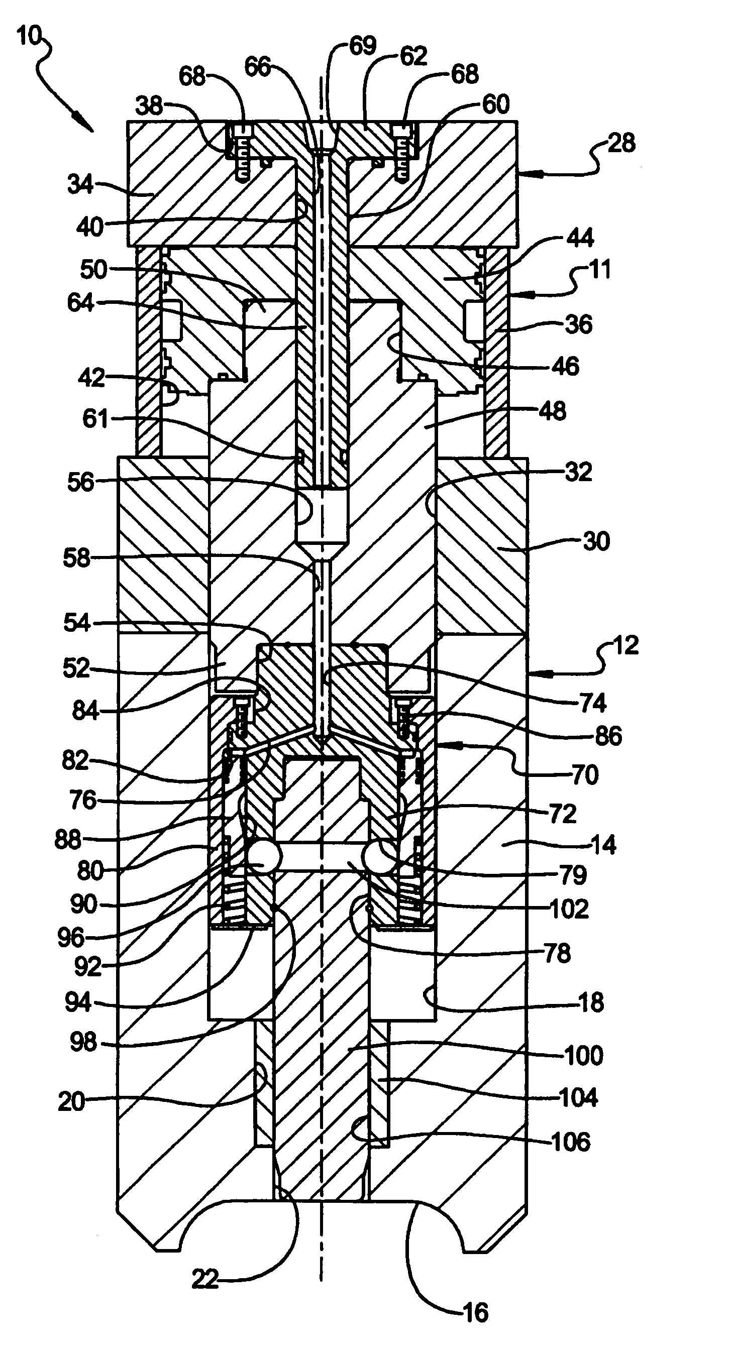
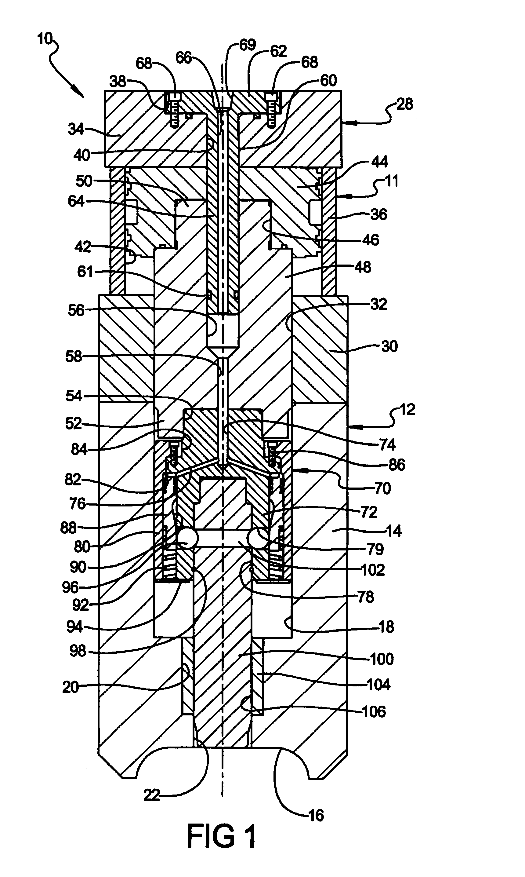
[0022]Referring to the drawings and in particular FIG. 1, one embodiment of a quick change assembly 10, according to the present invention, is generally shown for a punch assembly, generally indicated at 11, used with a hydroforming die, generally indicated at 12. The hydroforming die 12 is a die set comprised of a lower die half (not shown) and an upper die half 14. The lower die half and the upper die half 14 each include a tubular forming cavity portion 16. The upper die half 14 includes a first cavity 18 extending axially therein, a second cavity 20 extending axially from the first cavity 18 and having a diameter less than a diameter of the first cavity 18, and an aperture 22 extending axially from the second cavity 20 and therethrough to the tubular forming cavity portion 16. It should be appreciated that a combined cross-sectional circumferential measure of the tubular forming cavity portions total up to generally equal to or slightly greater than the cross-section of a tubula...


PUM


Abstract

A punch assembly used with a hydroforming die includes a punch cylinder for mounting to the hydroforming die and having a movable rod. The punch assembly also includes a punch for piercing an opening in a tubular member disposed in the hydroforming die. The punch assembly further includes a quick change assembly interconnecting the rod of the punch cylinder and the punch for allowing the punch to be removably attached to the punch cylinder.

Description

TECHNICAL FIELD[0001]The present invention relates generally to hydroforming and, more specifically, to a quick change assembly for hydroforming punches.BACKGROUND OF THE INVENTION[0002]It is known to form a cross-sectional profile of a tubular member by a hydro-forming process in which a fluid filled tubular blank is placed within a cavity of a die and then the die is closed so that the tubular blank is enclosed within the die. Fluid pressure is then increased inside the tubular member to expand the blank outwardly against the cavity of the die to provide a tubular product having a die formed cross-sectional profile.[0003]During tube hydroforming, punches of various shapes and sizes are used to create necessary openings in the tubular member. Hydraulic cylinders activate the motion of the punches. A solid mechanical mounting between the punch and a cylinder rod is necessary in order to provide the required strength needed for the piercing operation.[0004]As the request for hydrofor...

Claims


Application Information

Patent Timeline
IPC IPC(8): B21D53/88B21D26/02
CPCB21D26/035B21D28/28Y10T29/49805Y10T83/9476
Inventor GHIRAN, MIKE M.
Owner GM GLOBAL TECH OPERATIONS LLC
Why Eureka
Try Eureka