Miter box for guiding a circular saw

a technology of circular saw and miter box, which is applied in the direction of cross-cut reciprocating saws, portable power driven saws, metal working apparatus, etc., can solve the problems of difficult to make certain cuts using circular saws, difficult to maintain a steady cutting path, and inaccurate straightcuts and undercuts in a workpiece using a handheld portable circular saw. achieve the effect of greater stability of the miter box

Inactive Publication Date: 2007-01-09
STEWART DENHAM RAY
View PDF14 Cites 13 Cited by
  • Summary
  • Abstract
  • Description
  • Claims
  • Application Information

AI Technical Summary

Benefits of technology

[0015]Another embodiment of the invention can include two or more spacer elements that can be attached to the support faces in order to provide greater stability to the miter box.

Problems solved by technology

Moreover, making accurate and smooth straightcuts and undercuts in a workpiece using a handheld portable circular saw has been a long standing problem in the field.
Compounding the problem, the operational vibration caused by a handheld power saw makes it even more difficult to maintain a steady cutting path.
Also, it is sometimes difficult to make certain cuts using circular saws that are designed for right handed individuals
However, there are several disadvantages in using a miter saw.
First of all, miter saws are very expensive and are prone to be stolen or damaged at a construction site.
Second, they are difficult to transport given their bulky size and relatively heavy weight.
Moreover, given that the great majority of cuts used in trim carpentry work involve simple 45 and 90 degree angles, a miter saw's wide range of adjustable angle cuts would appear to be unnecessary for most types of trim work.
Another unresolved problem using miter boxes is that they are usually adapted for right-handed saw operation only.

Method used


Image

  • Miter box for guiding a circular saw
  • Miter box for guiding a circular saw
  • Miter box for guiding a circular saw

Examples


Embodiment Construction

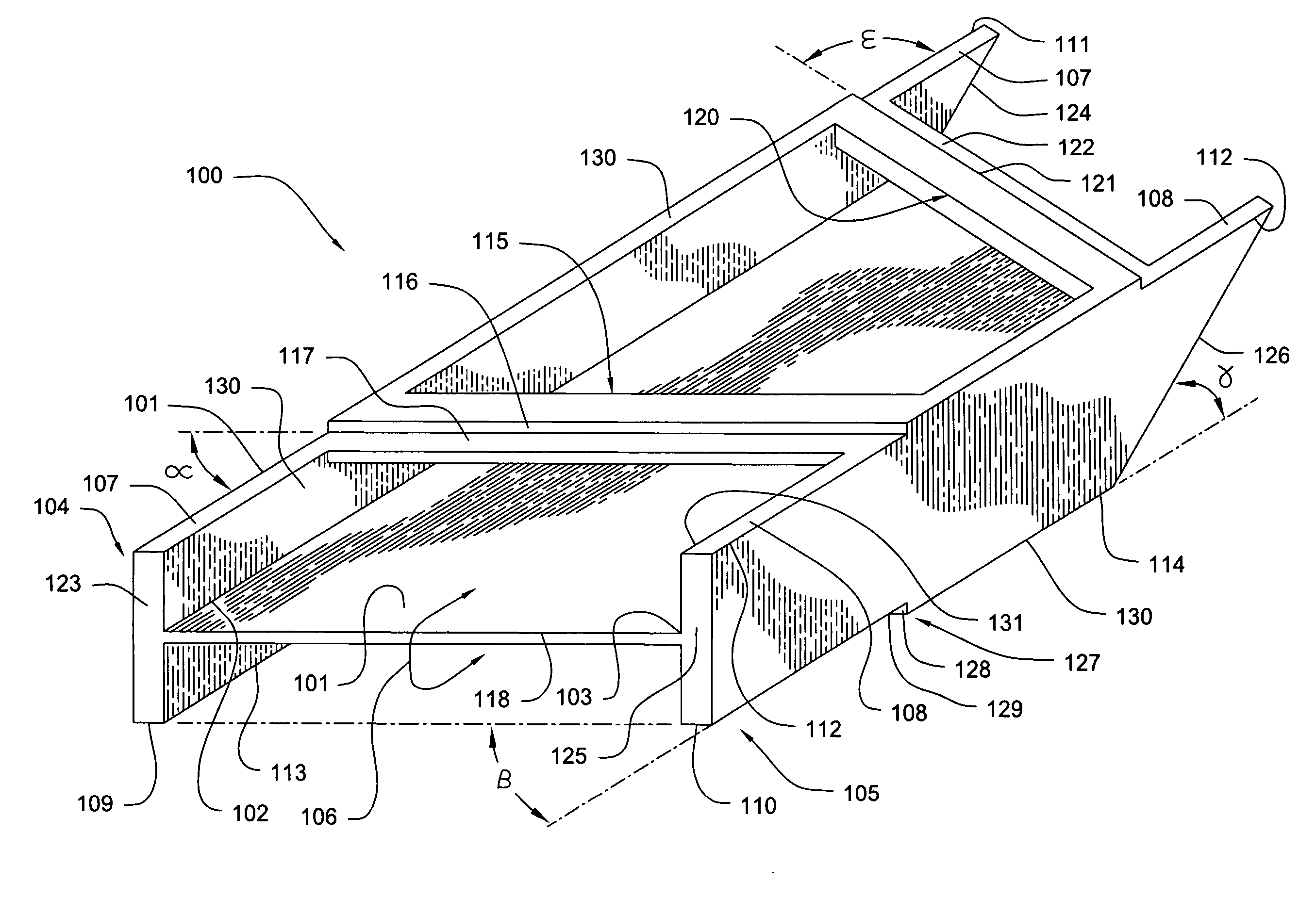
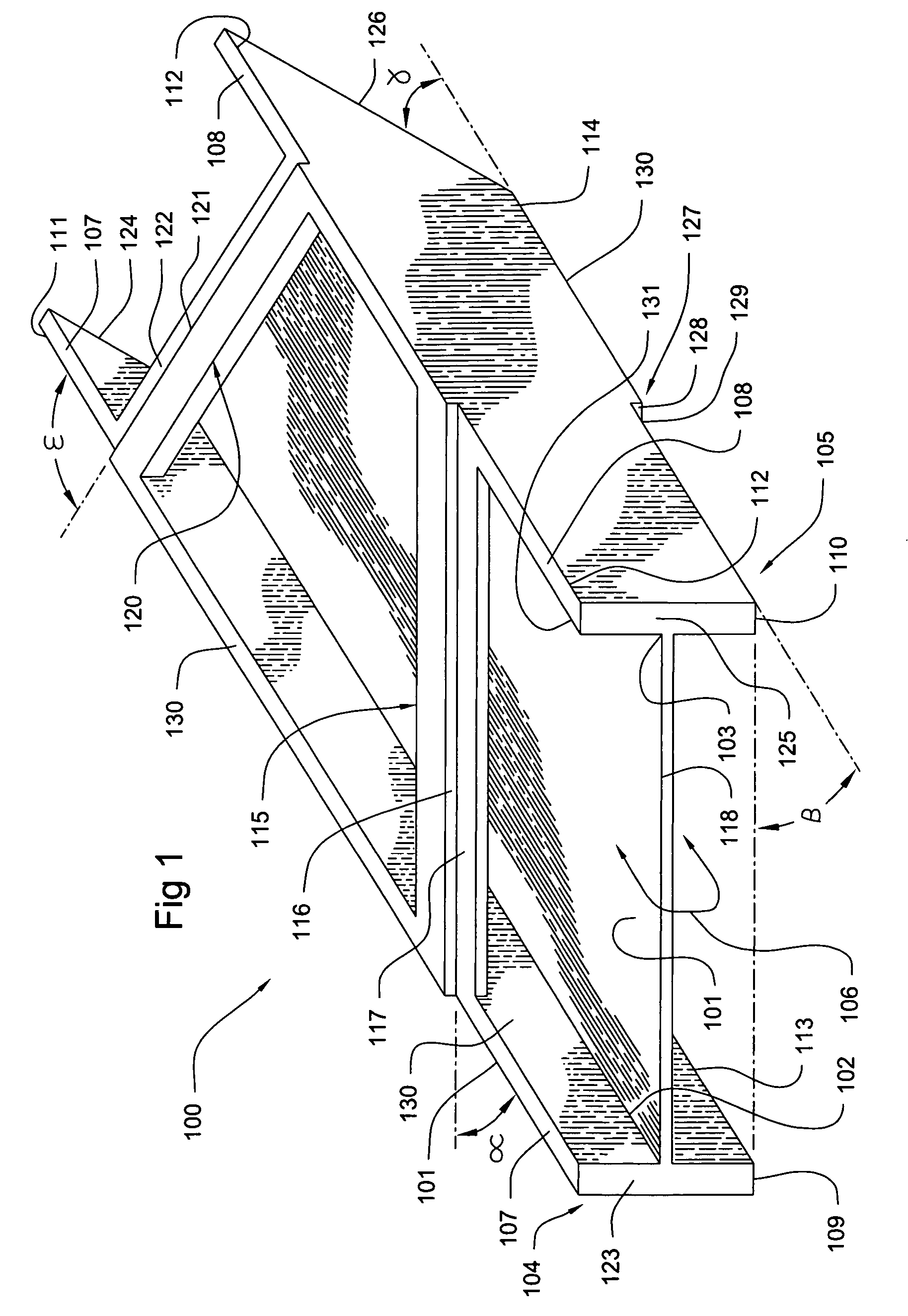
[0024]Referring particularly to FIG. 1, there is shown an improved miter box 100. The miter box 100 can include an I-beam comprised of a rigid base plate 101. The rigid base plate 101 can include opposing first and second base plate edges, 102 and 103 respectively. The first and second base plate edges 102, 103 can be disposed along an elongated length of the rigid base plate 101. The rigid base plate 101 and the miter box 100, in general, can be formed of molded plastic, wood, or metal. However, the invention is not limited in this regard and other materials may be used so long as the miter box 100 can provide a strong and durable surface to support the weight of a workpiece 206 to be cut, a circular saw's weight and vibration, and the pressure applied by the user to the miter box when operating the saw.

[0025]A first flange 104 and a second flange 105 can be respectively attached to the opposing first and second base plate edges 102, 103 along the elongated length of the rigid base...


PUM

PropertyMeasurementUnit
angleaaaaaaaaaa
angleaaaaaaaaaa
45 degree angleaaaaaaaaaa

Abstract

The invention relates to an improved miter box for guiding a handheld portable circular saw. The miter box facilitates several conventional workpiece trim cuts using a handheld portable circular saw, including 45 degree and 90 degree straightcuts, as well as 45 and 90 degree straightcuts with a 45 degree undercut. The invention includes an I-beam that is formed from a rigid base plate having opposing first and second base plate edges disposed along its elongated length. A first and second flange can be respectively attached to the opposing first and second base plate edges. Each of the flanges can include a pair of opposing support faces. One or more transverse guide members can extend either 45, 135, or 90 degrees from one support face of the first flange to another support face of the second flange. The transverse guide member(s) and the support faces provide a friction reduced medium by which the bottom of a handheld portable circular saw's shoe can glide with greater ease and stability.

Description

CROSS REFERENCE TO RELATED APPLICATIONS[0001]This application is a Continuation-in-part of U.S. application Ser. No. 10 / 397,091 filed on Jun. 16, 2003 now abandoned.BACKGROUND OF THE INVENTION[0002]1. Statement of the Technical Field[0003]The inventive arrangements relate to miter boxes for trim carpentry work. In particular, the invention relates to an improved miter box for guiding a handheld circular saw.[0004]2. Description of the Related Art[0005]In the field of trim carpentry work, it is desirable to use a saw guide or miter box to ensure a straight, smooth and accurate cut. Such cuts include 45 degree straightcuts to unite the corners of a door frame molding. Another example includes 90 degree straightcuts with a 45 degree undercut to unite baseboards at a corner of a room. Absent a saw guide or miter box, a user must typically mark a straight line in pencil with the help of a straightedge and protractor and attempt to manually guide the saw along the marked line. Moreover, m...

Claims


Application Information

Patent Timeline
Patent Type & Authority Patents(United States)
IPC IPC(8): B27B9/04B26B29/00B27G5/02
CPCB27G5/026Y10T83/68Y10T83/695Y10T83/8773Y10T83/8878
Inventor STEWART, DENHAM RAY
Owner STEWART DENHAM RAY
Why Eureka
Try Eureka