Start control for internal combustion engine
a technology of internal combustion engine and start control, which is applied in the direction of engine starters, electrical control, non-mechanical valves, etc., can solve the problems of small combustion torque, high friction generated at engine parts, and parts of the engine cannot be overcom
- Summary
- Abstract
- Description
- Claims
- Application Information
AI Technical Summary
Benefits of technology
Problems solved by technology
Method used
Image
Examples
first embodiment
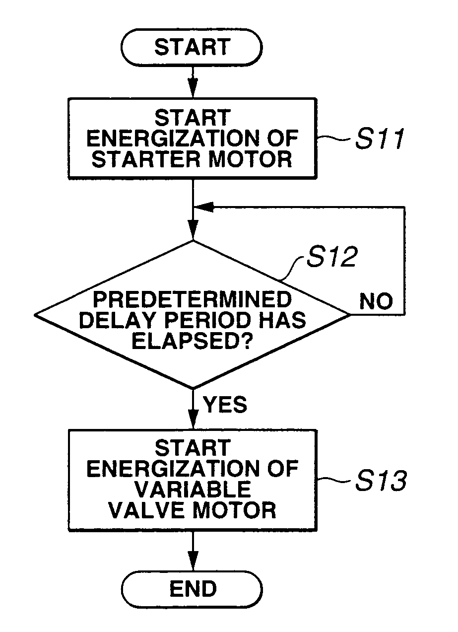
[0040]FIG. 9 is a flowchart showing an engine start control according to the present invention. This routine is performed in response to an engine start request made by engine start request input means, such as an operation of an ignition key. First, in step S11, an electric supply to starter motor 10 is started in response to the engine start request, and thus rotation of crankshaft CS by starter motor 10, i.e., cranking and engine start, is commenced (cranking part). In S12, it is determined whether or not a predetermined delay period corresponding to a crank angle Δt from an IVC to a compression TDC has elapsed since the start of the electric supply to starter motor 10. This delay period is equivalent to a period required by crankshaft CS to rotate by crank angle Δt from the start of the cranking, i.e., a period from the IVC to the compression TDC with a valve opening / closing characteristic for an engine stop state, and thus is a fixed value which is determined and stored beforeh...
third embodiment
[0045]FIG. 11 is a flowchart showing an engine start control according to the present invention. This routine is performed in accordance with an engine start request. First, in S31, an electric supply to starter motor 10 is started, and thereby cranking is commenced. In S32, it is determined whether or not any of the cylinders has the piston positioned within a region starting from an IVC toward an intake bottom dead center. That is, it is determined whether or not a piston position of any of the cylinders is within pressure increase region ΔP. When it is determined in S32 that any of the cylinders has a piston position within pressure increase region ΔP, the routine of FIG. 11 proceeds to S33. In S33, one of the cylinders having a piston position closest to the IVC is set to be a target cylinder. When it is determined in S32 that none of the cylinders has a piston position within pressure increase region ΔP, the routine of FIG. 11 proceeds to S34. In S34, one of the cylinders first...
PUM
 Abstract
Description
Claims
Application Information
 - R&D
- Intellectual Property
- Life Sciences
- Materials
- Tech Scout
- Unparalleled Data Quality
- Higher Quality Content
- 60% Fewer Hallucinations
Browse by: Latest US Patents, China's latest patents, Technical Efficacy Thesaurus, Application Domain, Technology Topic, Popular Technical Reports.
© 2025 PatSnap. All rights reserved.Legal|Privacy policy|Modern Slavery Act Transparency Statement|Sitemap|About US| Contact US: help@patsnap.com


