Start control for internal combustion engine

a technology of internal combustion engine and start control, which is applied in the direction of engine starters, electrical control, non-mechanical valves, etc., can solve the problems of small combustion torque, high friction generated at engine parts, and parts of the engine cannot be overcom

Active Publication Date: 2005-06-30
HITACHI ASTEMO LTD +1
View PDF6 Cites 26 Cited by
  • Summary
  • Abstract
  • Description
  • Claims
  • Application Information

AI Technical Summary

Benefits of technology

[0004] When the closing timing of the intake valve is at an advance angle from a bottom dead center of a piston, such as in a case of the intake lift characteristic being small-lift / small-angle at the engine start with a small valve lift amount and a small operative angle, the intake valve is closed before an air-fuel mixture is sufficiently supplied to a combustion chamber, and thereby reduces an air-fuel mixture charge. This results in a small combustion torque. With this small combustion torque, the high frictions at parts of the engine cannot be overcome to increase the engine speed, and thereby may cause an engine stall. When the closing timing of the intake valve is at a retard angle from the bottom dead center, such as in a case of the intake lift characteristic being large-lift / large-angle at the engine start, the air-fuel mixture once taken in the combustion chamber is discharged to an intake passage after the bottom dead center, and thereby reduces an air-fuel mixture charge in the combustion chamber. Therefore, as in the case of the small-lift / small-angle characteristic, a sufficient combustion torque cannot be achieved, and thereby aggravates the engine startability. Especially, in the case of the large-lift / large-angle characteristic, since frictions in a valve operating system are high, the engine startability is aggravated also in this respect. When the closing timing of the intake valve is in proximity of the bottom dead center, such as in a case of the intake lift characteristic being medium-lift / medium-angle at the engine start, an air-fuel mixture charge in the combustion chamber is large. This results in a large combustion torque. With this large combustion torque, the internal combustion engine can overcome the high frictions at parts of the engine, and can increase the engine speed. Thereby the internal combustion engine can quickly secure a stable combustion condition, and thus can achieve a favorable engine startability.
[0008] It is an object of the present invention to provide technique for controlling a valve opening / closing characteristic to a state suitable for cranking at an engine start, by using a variable valve operating mechanism, without causing an excessively sharp increase in power consumption by a variable valve motor and a starter motor.

Problems solved by technology

Upon an engine start, i.e., when a crankshaft is cranked by an electric starter motor, high frictions are generated at parts of the engine.
This results in a small combustion torque.
With this small combustion torque, the high frictions at parts of the engine cannot be overcome to increase the engine speed, and thereby may cause an engine stall.
Therefore, as in the case of the small-lift / small-angle characteristic, a sufficient combustion torque cannot be achieved, and thereby aggravates the engine startability.
This results in a large combustion torque.
However, at an early stage of the engine start corresponding approximately to one revolution of the cranking by the starter motor, a considerably large cranking torque is necessary to transfer a stop state of the crankshaft into a rotational state.
Therefore, if the variable valve motor is energized concurrently with the starter motor being energized to start the cranking, consumption current (power) temporarily undergoes a sharp increase.
This causes a shortage in electric supply to the starter motor and a failure to achieve the desired cranking torque, and may deteriorate the engine startability.

Method used


Image

  • Start control for internal combustion engine
  • Start control for internal combustion engine
  • Start control for internal combustion engine

Examples


first embodiment

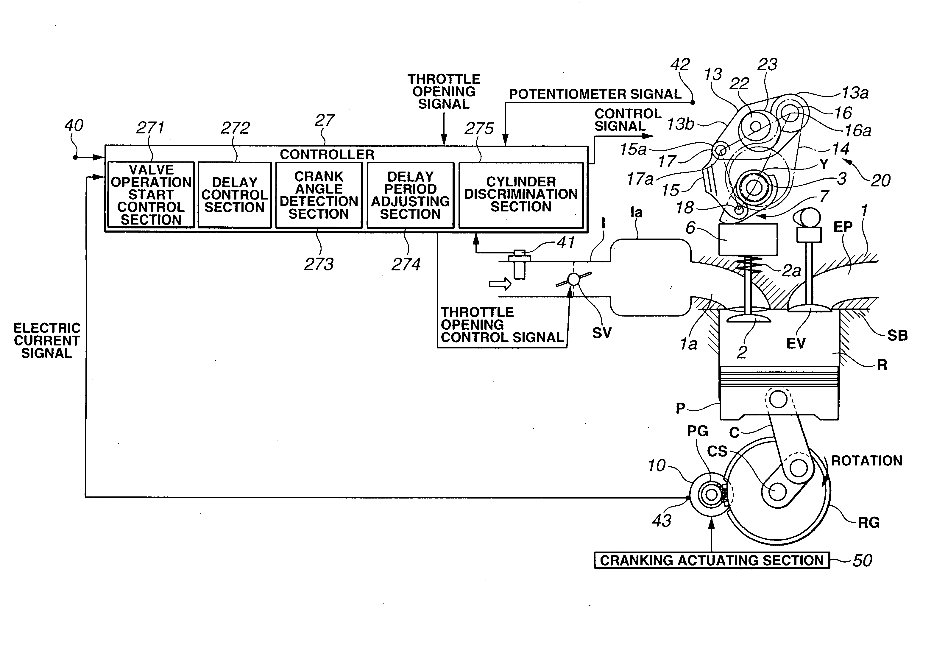
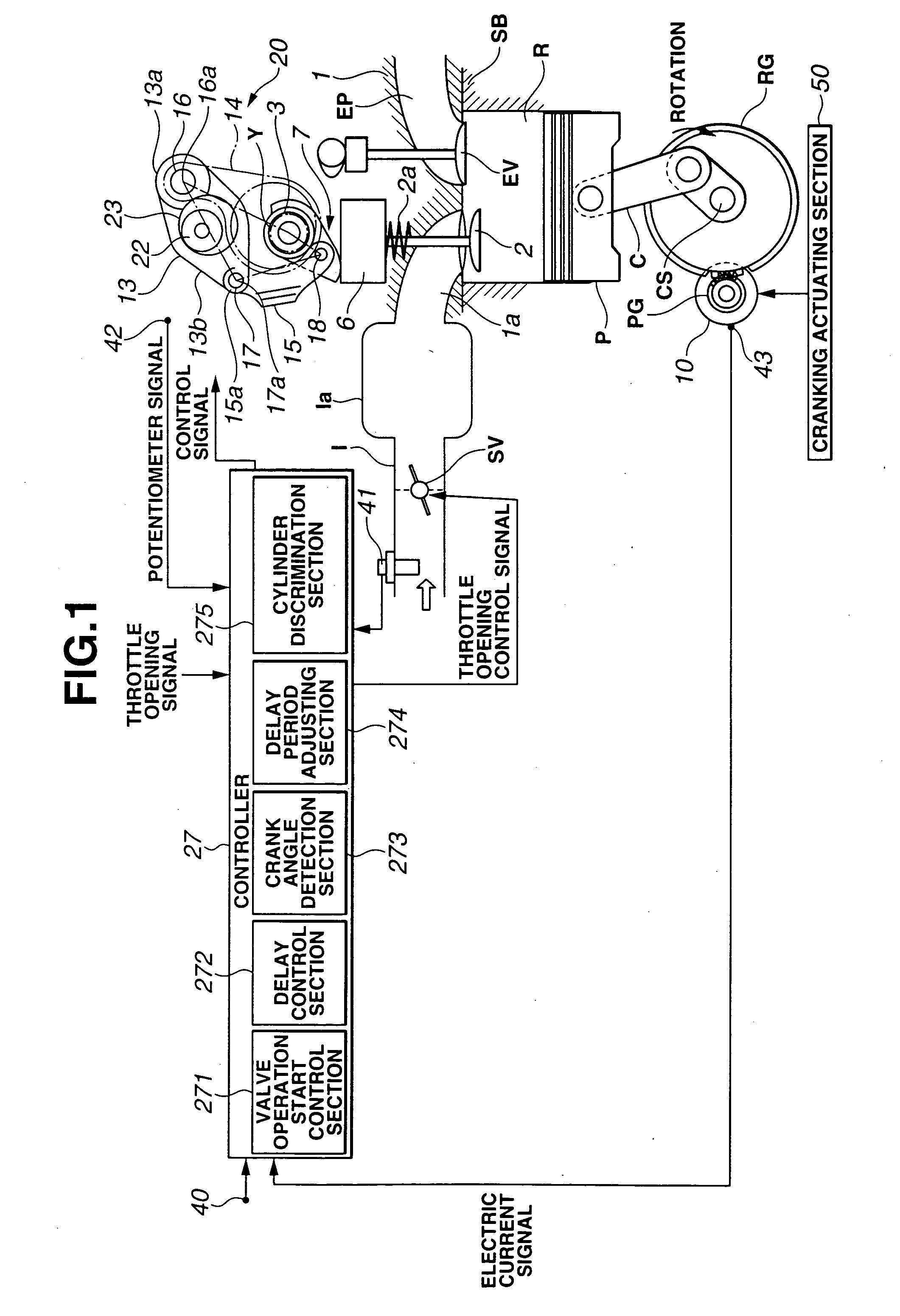
[0040]FIG. 9 is a flowchart showing an engine start control according to the present invention. This routine is performed in response to an engine start request made by engine start request input means, such as an operation of an ignition key. First, in step S11, an electric supply to starter motor 10 is started in response to the engine start request, and thus rotation of crankshaft CS by starter motor 10, i.e., cranking and engine start, is commenced (cranking part). In S12, it is determined whether or not a predetermined delay period corresponding to a crank angle Δt from an IVC to a compression TDC has elapsed since the start of the electric supply to starter motor 10. This delay period is equivalent to a period required by crankshaft CS to rotate by crank angle Δt from the start of the cranking, i.e., a period from the IVC to the compression TDC with a valve opening / closing characteristic for an engine stop state, and thus is a fixed value which is determined and stored beforeh...

third embodiment

[0045]FIG. 11 is a flowchart showing an engine start control according to the present invention. This routine is performed in accordance with an engine start request. First, in S31, an electric supply to starter motor 10 is started, and thereby cranking is commenced. In S32, it is determined whether or not any of the cylinders has the piston positioned within a region starting from an IVC toward an intake bottom dead center. That is, it is determined whether or not a piston position of any of the cylinders is within pressure increase region ΔP. When it is determined in S32 that any of the cylinders has a piston position within pressure increase region ΔP, the routine of FIG. 11 proceeds to S33. In S33, one of the cylinders having a piston position closest to the IVC is set to be a target cylinder. When it is determined in S32 that none of the cylinders has a piston position within pressure increase region ΔP, the routine of FIG. 11 proceeds to S34. In S34, one of the cylinders first...


PUM


Abstract

In an internal combustion engine, a starter motor is energized in response to a request for an engine start to perform a cranking of the internal combustion engine. Thereafter, an electric variable valve motor is energized to control a valve opening / closing characteristic to a condition designed to promote the cranking. The start of the energization of the electric variable valve motor is delayed from the start of the energization of the starter motor at least by a predetermined delay period.

Description

BACKGROUND OF THE INVENTION [0001] The present invention relates to start control technique for an internal combustion engine having a variable valve operating mechanism to vary a valve opening / closing characteristic. [0002] Internal combustion engines have been provided with various variable valve operating mechanisms to vary a valve opening / closing characteristic in accordance with an operating condition of the engine and thereby to improve a fuel economy at a low-revolution / light-load operation and an output torque at a high-revolution / heavy-load operation. Japanese Patent Application Publication No. 2000-234533 discloses a variable lift / angle mechanism capable of continuously varying both a valve lift amount and an operative angle of each intake valve. SUMMARY OF THE INVENTION [0003] Upon an engine start, i.e., when a crankshaft is cranked by an electric starter motor, high frictions are generated at parts of the engine. The high frictions originate from such factors as a low en...

Claims


Application Information

Patent Timeline
Patent Type & Authority Applications(United States)
IPC IPC(8): F01L13/00F01L9/04F02D13/02F02D43/00F02N11/08F02N19/00
CPCF01L13/0005F01L13/0026F02N19/004F02D2041/0012F01L2013/0073
Inventor NOHARA, TSUNEYASUAKASAKA, YUZOUTOMOGANE, KAZUTOISODA, KAZUTAKANAKAMURA, MAKOTOSUZUKI, AKINORI
Owner HITACHI ASTEMO LTD
Why Eureka
Try Eureka