Mounting arrangement and method

a technology of mounting arrangement and mounting method, which is applied in forging/pressing/hammering apparatus, forging/hammering/pressing machines, manufacturing tools, etc., can solve the problems of affecting the machining accuracy of the component, the residual stress cannot be relieved in the above forged component, and the final machine component may become distorted, etc., to achieve the effect of more accurate machining of the componen

Active Publication Date: 2007-01-09
ROLLS ROYCE PLC
View PDF20 Cites 2 Cited by
  • Summary
  • Abstract
  • Description
  • Claims
  • Application Information

AI Technical Summary

Benefits of technology

[0011]The method may comprise an initial machining process for removal of bulk material from a rough initial component and a final machining process with more resilient clamping of the component for more accurate machining of that component.

Problems solved by technology

Unfortunately, these machines are designed for high accuracy operation such that multiple abutment clamping of the component is necessary and normally a datum such as a flat surface is initially provided to the component to ensure surety of position and therefore machined accuracy in the final product.
Such robust and accurate assembly as indicated is highly beneficial with regard to high accuracy machining processes but with regard to machining initially rough forged components may be detrimental.
These residual stresses cannot be relieved in the above forged component due to the high strength clamping inherent in machines such as Heyligenstaedt four-axis turning machines for accurate forming.
In such circumstances, when the multi abutment clamping is released the final machine component may become distorted as these residual stresses are then relieved.
Such distortion clearly detracts from the desired shape profile for the component in its finished state.

Method used


Image

  • Mounting arrangement and method
  • Mounting arrangement and method
  • Mounting arrangement and method

Examples


Embodiment Construction

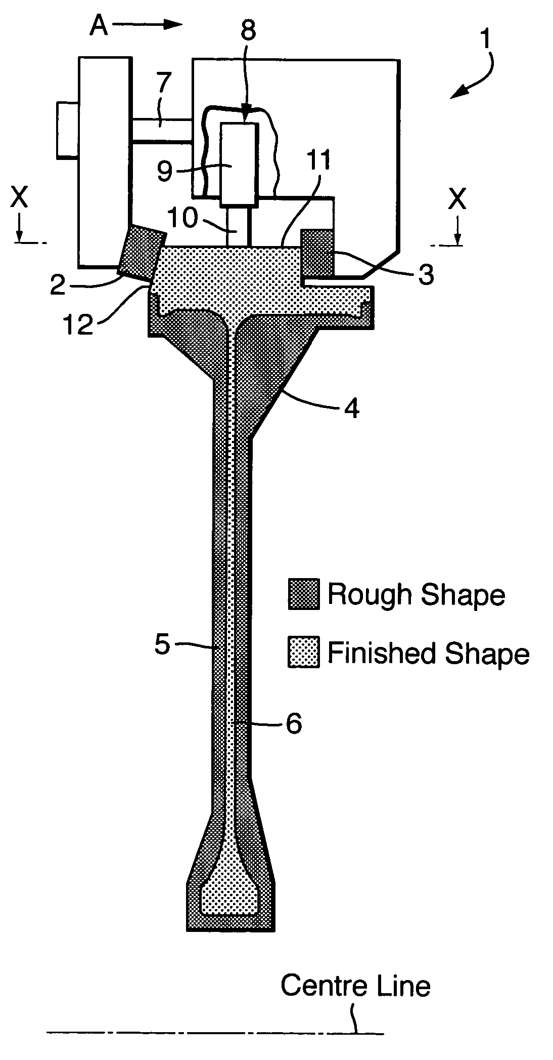
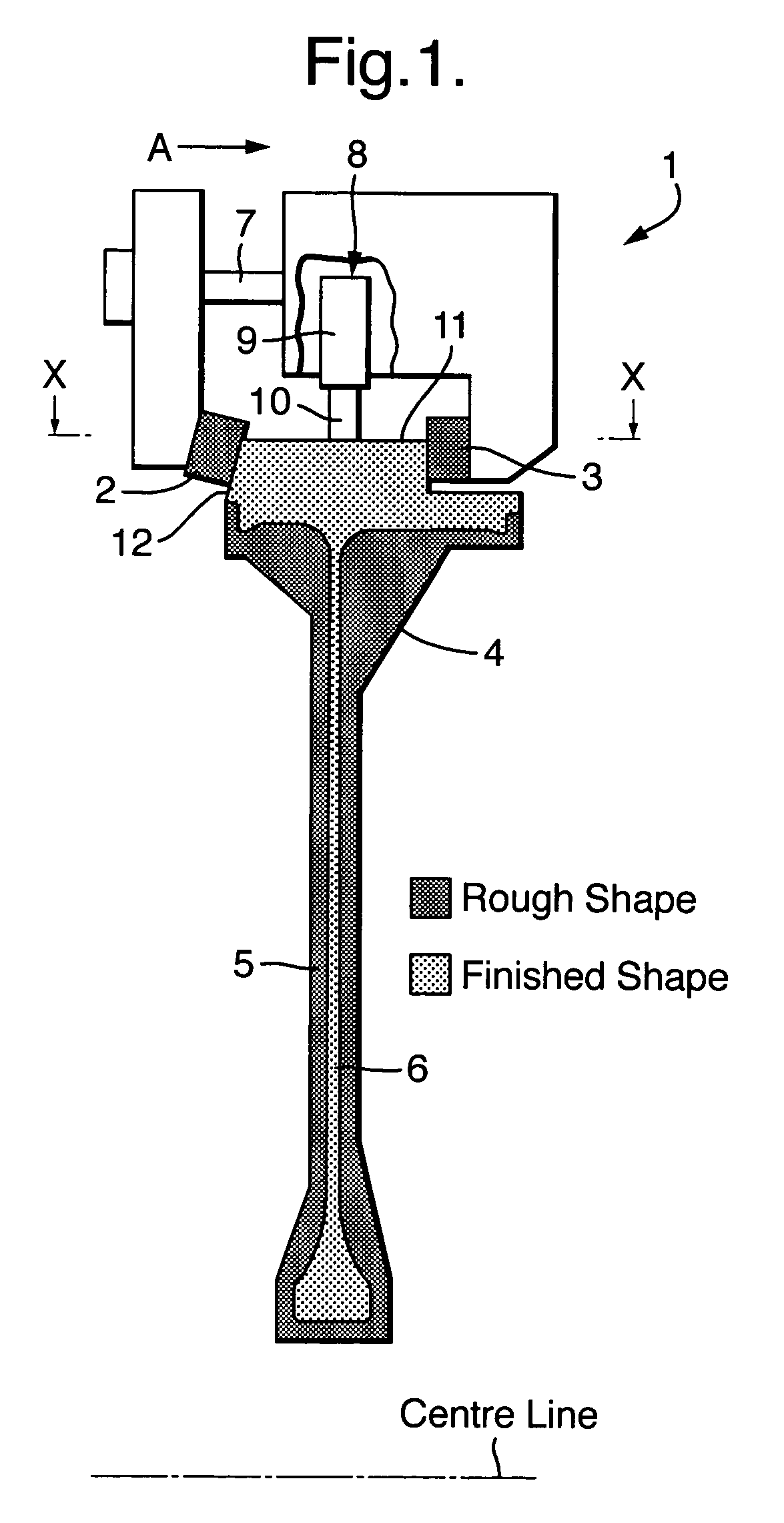
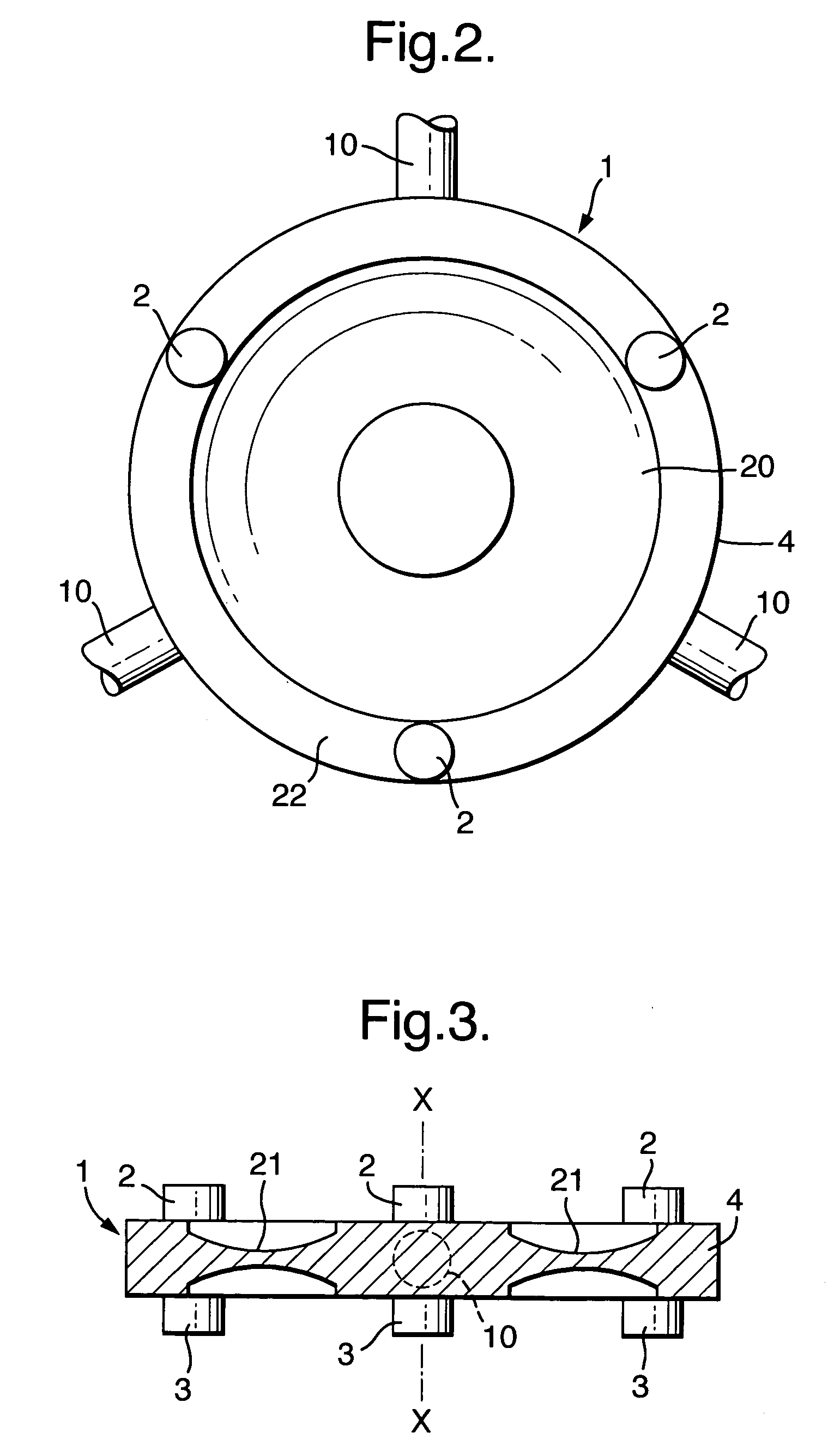
[0016]Referring to FIG. 1 which is a schematic cross-section of a mounting arrangement 1 in accordance with the present invention. Thus, the arrangement 1 comprises a clamp pair formed by abutment contact between a clamping pad 2 and a seat pad 3. The clamp pair creates a contact abutment in order to clamp a component 4. This component 4 as illustrated in FIG. 1 is initially a rough forged component with an outline profile 5 but upon machining by means not depicted is rendered with a finished profile 6. Such machining can be by turning or other technique as required. The component will be turned relative to a tool.

[0017]In order to provide clamping force an axial movement in the direction of arrowhead A is provided such that contact abutment is achieved between the clamping pad 2 and seating pad 3. Generally, this axial movement in the direction of arrowhead A will be through a screw thread 7 driven by a worm gear or otherwise in order to create the necessary clamping force across t...


PUM

PropertyMeasurementUnit
angleaaaaaaaaaa
residual stressesaaaaaaaaaa
residual stressaaaaaaaaaa

Abstract

A mounting arrangement 1 is provided in which clamping pairs comprising a clamping pad 2 and seating pads 3 are arranged about a mounting end of a component 4. Thus, the component 4 is appropriately presented to a machining device but the component 4 can slip relative to the pads 2, 3 in order to relieve residual stresses in the component due to initial forging processes. A damper 8 is provided in order to augment vibration control in association with the contact abutments between the pads 2, 3. In such circumstances accurate machining of a component 4 to a final profile 6 from an initial rough profile 5 can be achieved more efficiently without periodic release of the component 4 so that distortions are avoided in the final component as a result of retained residual stresses by previous clamping.

Description

FIELD OF THE INVENTION[0001]The present invention relates to mounting arrangements for and methods of machining components such as turbine discs and compressor discs which may retain residual stresses after initial forging.BACKGROUND OF THE INVENTION[0002]A number of components are initially cast or forged into an approximate shape for the final finished component. Such an approach allows ease of manufacture as well as potential crystallography and material treatment to be achieved conveniently. The forged component such as a turbine disc is then machined appropriately in order to achieve the final component shape and surface finish. Generally the original forged component only provides a rough approximation to the final finished shape and so a significant proportion of the forged material must be removed in order to achieve the desired finished shape.[0003]Machining of the forged component is typically through milling, turning or broaching whereby material is removed from the rough...

Claims


Application Information

Patent Timeline
Patent Type & Authority Patents(United States)
IPC IPC(8): B23Q3/00B25B5/14
CPCB25B5/14Y10T409/309016Y10T409/303808Y10T409/304312Y10T82/10
Inventor BAKER, IAN J
Owner ROLLS ROYCE PLC
Why Eureka
Try Eureka