System and method for initializing a network attached storage system for disaster recovery

a network attached storage and disaster recovery technology, applied in the field of network attached storage systems, can solve the problems of inability to communicate with network administrators regarding the availability of resources and particular system requirements, lack of crucial details, and difficulty in recognizing the capabilities and requirements of the network attached storage, so as to improve the accuracy of mapping, improve the accuracy of the mapping, and improve the speed

Active Publication Date: 2014-04-15
EMC IP HLDG CO LLC
View PDF8 Cites 7 Cited by
  • Summary
  • Abstract
  • Description
  • Claims
  • Application Information

AI Technical Summary

Benefits of technology

[0009]Such an arrangement enables high speed, accurate identification of components for use in a backup NAS. Ensuring that only the secondary components having the adequate capabilities are considered as standby candidates greatly improves the accuracy of mappings, raising confidence that disaster recovery can truly be supported. In addition, because the present invention uses configuration information that is retrieved directly from the primary and secondary NAS when identifying potential secondary components, candidate identification may be quickly done in software, without regard the number, versions and types of components that are provided in either the primary or secondary NAS.

Problems solved by technology

Current methods of initializing primary and secondary NAS relationships for disaster recovery lack coordination; typically network administrators at each site perform manual mappings using scripts that are tailored to the particular architecture of each NAS.
The primary and secondary NAS are typically geographically remote, and communication between the network administrators regarding the available resources and particular system requirements may be difficult and lack crucial detail.
As the types and versions of NAS components continue to grow, it can often be difficult for network administrators to comprehend the capabilities and requirements of the NAS.
As a result, components of a primary NAS may be erroneously mapped to components in a backup NAS that do not support its feature set.
Such incompatible mappings result are often not evident until disaster recovery is attempted, at which time it may be too late to salvage all file system data.

Method used


Image

  • System and method for initializing a network attached storage system for disaster recovery
  • System and method for initializing a network attached storage system for disaster recovery
  • System and method for initializing a network attached storage system for disaster recovery

Examples


Embodiment Construction

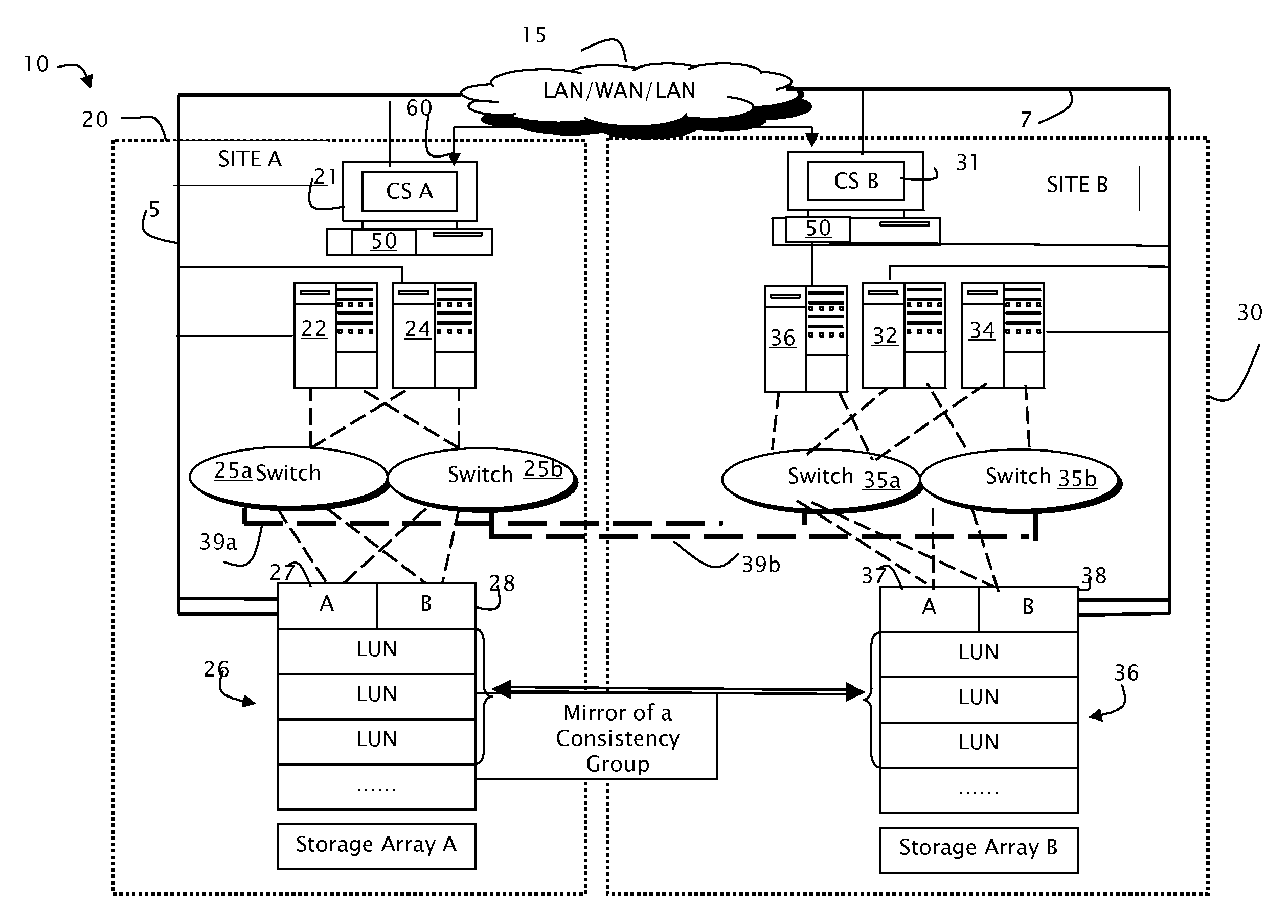
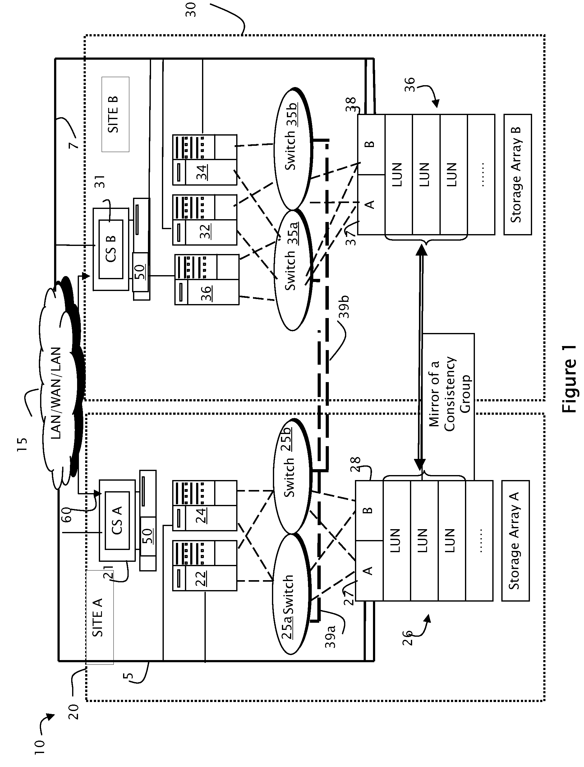
[0016]FIG. 1 is a block diagram that illustrates exemplary storage components that may be provided at two different sites that provide Network Attached Storage (NAS). As mentioned above, Network Attached Storage (NAS) is a term used to describe a complete NAS which is designed to be attached to a traditional data network such as the LANs 5, 7 and WAN 15.

[0017]Each NAS system site includes a front end file server and a back-end comprising one or more disk arrays 26. In one embodiment, the NAS system may be Celerra® Server provided by EMC2® Corporation of Hopkinton Mass., which includes one or more front end Data Mover devices (DMs) 22 and 24 and a back-end comprising a highly available disk array subsystem connected via fibre channel ports 27 and 28.

[0018]The file server DMs control the movement of data from the disk arrays to the network in response to NFS / CFIS commands received on the LANs 5, 7. The DMs communicate with the fibre channel ports 27 and 28 using Fibre Channel connecti...


PUM


Abstract

A method and system for initializing a Network Attached Storage (NAS) system having disaster recovery capabilities uses a communication link disposed between control stations of a source and destination NAS to enable the destination NAS to consolidate configuration and mapping information at a centralized location, thereby enabling validation of disk mirroring and mapping of standby components to be performed in a consistent manner.

Description

RELATED APPLICATIONS[0001]This application is a continuation-in-part and claims priority under 37 C.F.R. §1.20 to patent application Ser. No. 11 / 616,342 filed Dec. 27, 2006 now U.S. Pat. No. 8,234,465 and entitled “Disaster Recovery Using Mirrored Network Attached Storage”, incorporated herein by reference.FIELD OF THE INVENTION[0002]This invention relates generally to Network Attached Storage (NAS) systems and more particularly a method and apparatus for initializing a mirrored NAS for disaster recovery.BACKGROUND OF THE INVENTION[0003]Most organizations have a storage system that includes one or more disks or disk arrays for storing file systems for the organization, and one or more file servers which control accesses to the disks. For example, in a Storage Attached Network (SAN) system, external file servers communicate with one or more disk arrays using a Fibre Channel block protocol.[0004]Network Attached Storage (NAS) systems provide an integrated file servers / disk array solut...

Claims


Application Information

Patent Timeline
Patent Type & Authority Patents(United States)
IPC IPC(8): G06F17/30
CPCG06F11/2069G06F11/2064G06F11/2074
Inventor SRINIVASAN, KARTHIKEYANDEAN, ROYCE T.TIAN, XUN
Owner EMC IP HLDG CO LLC
Why Eureka
Try Eureka