Continuously variable transmission apparatus

a transmission apparatus and continuously variable technology, applied in the direction of friction gearings, gearing elements, friction gearings, etc., can solve the problems of increasing the amount of time required for stepping on the brake pedal during the vehicle stop, increasing the amount of time required for stepping on the brake pedal, and causing the driver to experience an uncomfortable feeling. to achieve the effect of preventing the providing of an uncomfortable feeling

Inactive Publication Date: 2007-01-09
NSK LTD
View PDF11 Cites 157 Cited by
  • Summary
  • Abstract
  • Description
  • Claims
  • Application Information

AI Technical Summary

Benefits of technology

[0060]In the case of a continuously variable transmission apparatus constituted as described above, when a travel state is selected so as to stop a vehicle or to drive at a low speed, as in the case of the constitution of FIG. 11 described hitherto, a transmission ratio (speed ratio) of a toroidal continuously variable transmission is adjusted so as to regulate a torque passing through the toroidal continuously variable transmission to thus prevent providing an uncomfortable feeling to a driver. Further, in the case where a non-travel state is selected, or immediately after that a travel state is selected from a non-travel state, when the torque passing through the toroidal continuously variable transmission 25a fails to become stable, control of the transmission ratio of the toroidal continuously variable transmission is stopped. Therefore, the transmission ratio of the toroidal continuously variable transmission is prevented from being excessively corrected, and the continuously variable transmission apparatus is prevented from providing an uncomfortable feeling to a driver because an excessive torque is transmitted to an output shaft when switched to a travel state.

Problems solved by technology

Accordingly, unless the transmission ratio of the toroidal continuously variable transmission 25 is adjusted strictly, the driver may experience an uncomfortable feeling, or drivability may be poor.
Under such a state, when the transmission ratio of the toroidal continuously variable transmission 25 is not adjusted strictly and a large torque is applied on the output shaft 38, a force required for stepping on the brake pedal during the vehicle stop becomes larger, thereby increasing driver fatigue.
However, in the case of the structure disclosed in JP-A-10-103461, because the control relies on only a pressure differential, stopping a posture of the trunnion at the moment when the passing torque has reached the desired value is difficult.
More specifically, because a displacement amount of the trunnion becomes large in order to control the torque, there easily occurs so-called overshoot (and hunting resulting from the overshoot).
Hence, control of the passing torque is not stable.
Therefore, an allowable range for adjusting the speed ratio is limited to a range where strain is not applied on the contact portions, which is a stricter limitation than that imposed in the case of low-speed driving.
More specifically, the speed ratio may be corrected excessively because of a failure to control the transmission ratio (speed ratio) based on the torque passing through the toroidal continuously variable transmission 25.

Method used


Image

  • Continuously variable transmission apparatus
  • Continuously variable transmission apparatus
  • Continuously variable transmission apparatus

Examples


first embodiment

[First Embodiment]

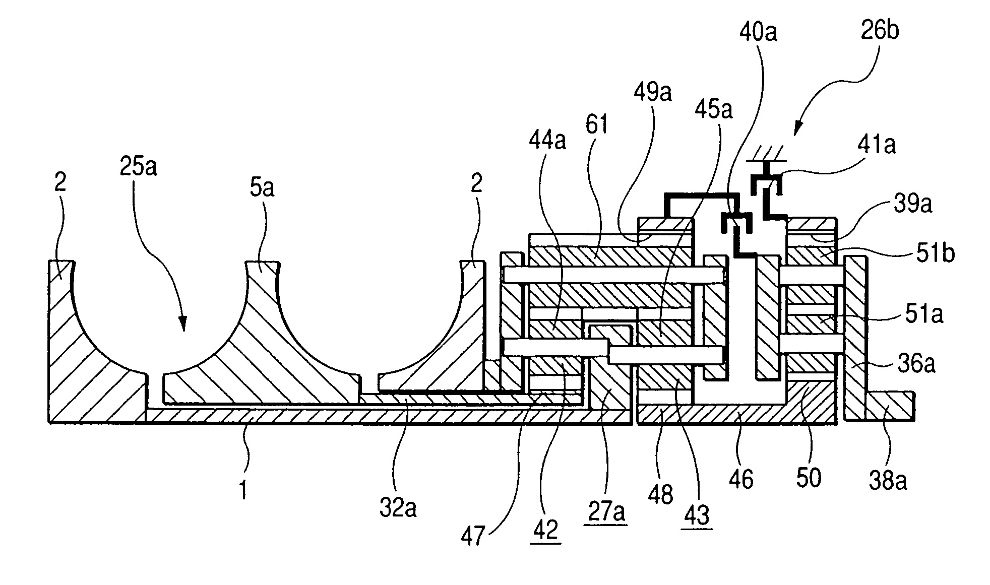
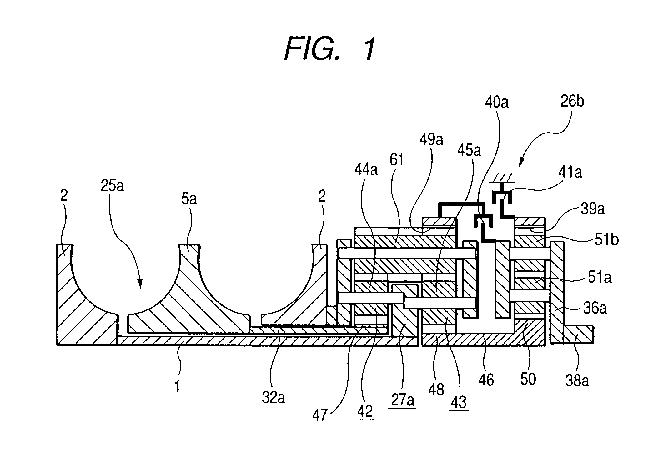
[0082]FIGS. 1 through 4 show a first embodiment of the invention. As shown in FIG. 1, a continuously variable transmission is constituted by combining a toroidal continuously variable transmission 25a and a planetary-gear-type transmission 26b of a differential unit. The constitution of the continuously variable transmission is principally the same as that of the continuously variable transmission of aforementioned conventional constitution shown in FIG. 10, or the structure shown in FIG. 11. In the continuously variable transmission of the embodiment, a planetary gear element—which is longer in an axial direction among the planetary gear elements constituting first and second planetary gears 42, 43 of the planetary-gear-type transmission 26b—is used as a planetary gear element 61 and provided on the outer side with respect to a radial direction. The planetary gear element 61 is meshed with planetary gear elements 44a, 45a provided on the inner side with respect to...

second embodiment

[Second Embodiment]

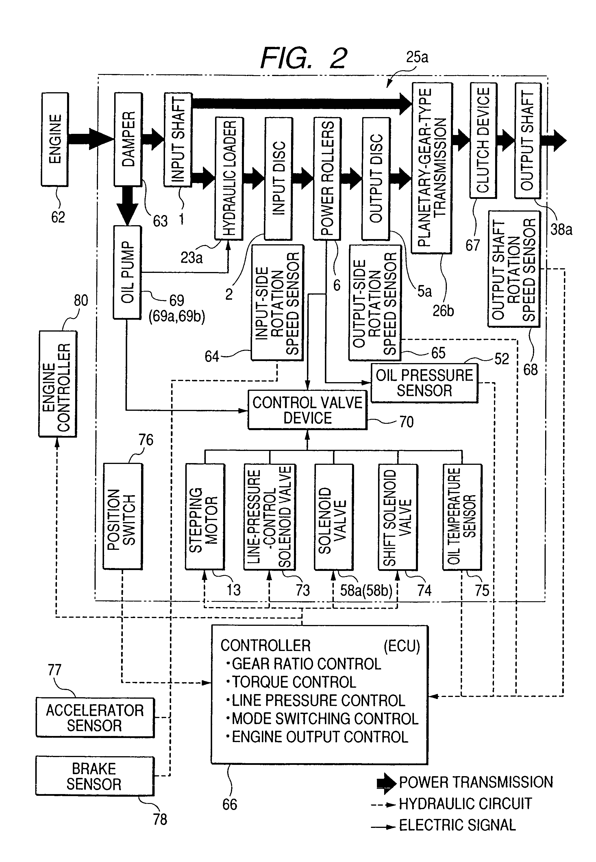
[0108]Next, FIG. 5 shows a flow chart for describing operation of a second embodiment of the invention. In the second embodiment, correction by a correcting control valve 57 (see FIG. 4) is started after an oil pressure differential between a pair of oil pressure chambers 24a, 24b provided in an actuator 10 has reached a predetermined value. As described above, an oil pressure differential between the pair of oil pressure chambers 24a, 24b is proportional to a torque passing through the toroidal continuously variable transmission 25a (see FIGS. 1 and 2). Accordingly, by observing the oil pressure differential, engagement of a clutch device 67 (FIG. 2) and stabilization of the torque can be detected. Accordingly, the correction is arranged so as to start when the oil pressure differential indicates that the torque has become stable. After the correction is started, the torque which is transmitted to the output shaft 38a after passing through the toroidal continuous...

third embodiment

[Third Embodiment]

[0109]Next, FIG. 6 shows a flow chart for describing operation of a third embodiment of the invention. In the third embodiment, a load-detecting device for detecting a load on the driving source engine 62 (FIG. 2) is provided. The engine controller 80 (FIG. 2) can be utilized as the load-detecting unit. That is, an increase in the load on the engine can be detected by utilizing a signal for directing that the fuel amount to be supplied to the engine should be increased, which is output from the engine controller 80 when a load on the engine 62 is increased. Then, on the basis of the increase in the load on the engine 62, engagement of the clutch device 67 (FIG. 2) and stabilization of the torque passing through the toroidal continuously variable transmission 25a (see FIGS. 1 and 2) can be detected. Therefore, the correction is arranged so as to start when the increase in the load of the engine 62 indicates that the torque has become stable. After the correction is ...


PUM


Abstract

A continuously variable transmission apparatus includes: an input shaft, an output shaft, a toroidal continuously variable transmission, a gear-type differential unit including a plurality of gears, and a controller. The controller calculates a torque actually passing through the toroidal continuously variable transmission to obtain a deviation of the torque from a target value and adjusts a transmission ratio of the toroidal continuously variable transmission to eliminate the deviation. The controller stops the adjustment of the transmission ratio when the torque is not stable.

Description

BACKGROUND OF THE INVENTION[0001]1. Field of the Invention[0002]The present invention relates to improvement of a continuously variable transmission apparatus, for use in an automatic transmission for a vehicle (automobile), in which a toroidal continuously variable transmission is incorporated. Particularly, the invention relates to a continuously variable transmission apparatus to which is added a function of improving characteristics during a vehicle stop or during very low speed driving while implementing a structure which avoids providing a driver with an uncomfortable feeling at vehicle start.[0003]2. Background Art[0004]A toroidal-type continuously variable transmission as shown in FIGS. 7 to 9 has been investigated as an automatic transmission for a vehicle, and has found limited use. The toroidal continuously variable transmission is referred to as a double cavity type, in which input discs 2, 2 are supported on peripheries of both end portions of an input shaft 1 via ball ...

Claims


Application Information

Patent Timeline
Patent Type & Authority Patents(United States)
IPC IPC(8): F16H37/12F16H37/02F16H15/38F16H37/08F16H61/02F16H61/662F16H61/664
CPCF16H61/6648F16H37/086Y10T477/619F16H2037/0886F16H61/6649
Inventor SHINOJIMA, TAKUMIINOUE, EIJI
Owner NSK LTD
Why Eureka
Try Eureka